SRM Current Controller with PWM Generation
Current controller with internal pulse width modulation for switched reluctance machines
Libraries:
Simscape /
Electrical /
Control /
SRM Control
Description
The SRM Current Controller with PWM Generation block performs discrete-time proportional-integral (PI) current control for the Switched Reluctance Machine (SRM) block. The block includes pulse width modulation (PWM).
PWM Generation Model
The figure shows the converter structure for an SRM.
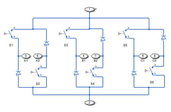
As the figure shows, the PWM generation signal is for high side switching devices.

When the control signal is greater than the carrier counter value, the PWM generator outputs 1. Otherwise, it outputs 0.
Equations
To determine the duty cycle, the block implements PI current control in the rotor reference frame in accordance with this equation.
Where:
D is the duty cycle.
Kp is the proportional gain.
Ki is the integral gain.
Ts is the sample time.
Is_ref is the reference current.
Is is the measured current.
To obtain control signals for the three-phases, the block then multiplies the duty cycle with the commutation signals. The resulting three control signals are normalized over the interval [0, 1].
Examples
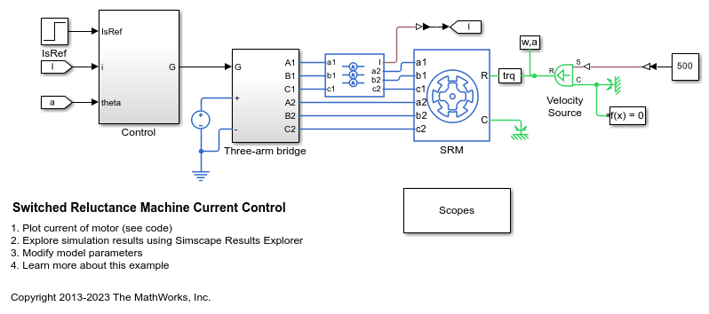
Switched Reluctance Machine Current Control
Control the current amplitude in a switched reluctance machine (SRM) based electrical drive. A DC voltage source feeds the SRM through a controlled three-arm bridge. An ideal angular velocity source provides the load. The converter turn-on and turn-off angles are maintained constant. A PI-based current controller regulates the current amplitude.
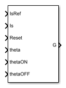
Ports
Input
Output
Parameters
References
[1] Saha, N. and S. Panda. "Speed control with torque ripple reduction of switched reluctance motor by Hybrid Many Optimizing Liaison Gravitational Search technique." Engineering Science and Technology. Vol 20 (2017): 909–921.
Extended Capabilities
Version History
Introduced in R2018a