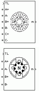
Stepper Motor
(To be removed) Implement stepper motor model
The Specialized Power Systems library will be removed in R2026a. Use the Simscape™ Electrical™ blocks and functions instead. For more information on updating your models, see Upgrade Specialized Power System Models to use Simscape Electrical Blocks.
Libraries:
Simscape /
Electrical /
Specialized Power Systems /
Electrical Machines
Description
The Stepper Motor (STM) block implements a generic model that represents two most popular families of stepper motors:
Variable-reluctance stepper motors
Permanent-magnet or hybrid stepper motors
The Stepper Motor model consists of electrical and mechanical sections. The electrical section is represented by an equivalent circuit, configuration of which depends on the motor type. The equivalent circuits assume that the magnetic circuit is linear (no saturation) and the mutual inductance between phases is negligible. The mechanical section is represented by a state-space model based on inertia moment and viscous friction coefficient.
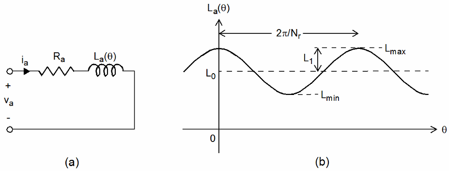
This figure shows the equivalent circuit for one phase in a variable-reluctance stepper motor.

In this model, Ra and La(θ), respectively, represent the resistance and the inductance of phase A winding. The winding inductance varies as a function of the rotor position:
| La(θ) = L0 + L1cos(Nrθ), | (1) |
where,
L0 is the average inductance.
L1 is the maximum inductance variation.
Nr is the rotor teeth number.
At the reference position (θ = 0), the rotor tooth is fully aligned with the A-axis pole to achieve the maximum A-phase winding inductance.
The total electromagnetic torque produced by the motor is the sum of the torques produced by the motor phases:
where,
m is the number of phases.
ix is the winding current in phase x.
Lx is the inductance function of phase x winding.
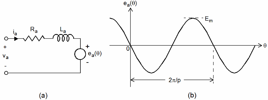
This figure shows the equivalent circuit for one phase in a permanent-magnet (PM) or hybrid stepper motor.

In this model, Ra and La, respectively, represent the resistance and inductance of A-phase winding. Due to the large value of the air gap introduced by the magnets, the winding inductance of the PM or hybrid stepper motor can be considered to be independent of the rotor position. The voltage source ea(θ) represents the motor back electromotive force (EMF), which is a sinusoidal function of the rotor position:
where,
p is the number of pole pairs. The number of pole pairs p is given by p = Nr/2.
ψm is the motor maximum magnetic flux.
Note that at the reference position (θ = 0), the north pole on the rotor is fully aligned with the A-axis pole to achieve zero value of the A-phase back EMF.
The electromagnetic torque produced by a two-phase PM or hybrid stepper motor is equal to the sum of the torque resulting from the interaction of the phase currents and magnetic fluxes created by the magnets and the detent torque, which results from the saliency of the rotor:
| Te = –pψmiasin(pθ) – pψmibsin(pθ – π/2) – Tdmsin(mNrθ). | (2) |
where,
m is the number of phase (m=2) of the motor.
Nr the number of teeth on the rotor (Nr = 2*p).
How to Get Stepper Motor Parameters
The parameters used in the stepper model are usually obtained from the manufacturer data sheets. In case the parameters are not available, you can determine them from experimental measurements.
The parameters provided by manufacturer data sheets are usually: number of phases, holding torque, step angle, voltage per phase, current per phase, winding resistance, Ra, maximum inductance, Lmax, average inductance, L0, and rotor inertia, J.
The parameters provided by manufacturer data sheets are usually:
number of phases
holding torque
step angle
voltage per phase
current per phase
winding resistance, Ra
winding inductance, La
rotor inertia, J
The maximum detent torque, Tdm, is not always specified. This parameter can be assumed to be equal to 1-10% of the maximum holding torque.
The maximum flux linkage, ψm, is not always specified. This parameter can be obtained experimentally by driving the motor to a constant speed, N, in rpm, and by measuring the maximum open-circuit winding voltage, Em, in V.
The parameter ψm is then computed by the following relation:
| ψm = (30/pπ)(Em/N), | (3) |
where p is the number of pole pairs given by p =360 / (2m·step). Here m = phase number, step = step angle in degrees.
Ports
Input
Output
Conserving
Parameters
References
[1] T. Kenjo, A. Sugawara, Stepping Motors and Their Microprocessor Controls, 2nd Edition, Oxford University Press, Oxford, 2003.
[2] P. Acarnley, Stepping Motors - A guide to theory and practice, 4th Edition, The Institution of Electrical Engineers, London, 2002.
Extended Capabilities
Version History
Introduced in R2008a
