Load Flow Bus
(To be removed) Identify and parameterize load flow bus
The Specialized Power Systems library will be removed in R2026a. Use the Simscape™ Electrical™ blocks and functions instead. For more information on updating your models, see Upgrade Specialized Power Systems Models to use Simscape Electrical Blocks.
Libraries:
Simscape /
Electrical /
Specialized Power Systems /
Utilities
Description
You use the Load Flow Bus block in models to specify the bus locations and parameters to solve a load flow. The Powergui Load Flow tool solves the load flow. Simscape Electrical Specialized Power Systems allows you to perform two types of load flows:
Positive-sequence load flow applied to a three-phase system. Positive-sequence voltages as well as active power (P) and reactive power (Q) flows are computed at each three-phase bus.
Unbalanced load flow applied to a mix of three-phase, two-phase, and single-phase systems. Individual phase voltage and PQ flow are computed for each phase.
To perform a positive-sequence load flow, you must define all of the Load
Flow Bus blocks in your model with the
Connectors parameter set to
single. For this type of load flow, the load flow
blocks are:
Asynchronous Machine
Simplified Synchronous Machine
Synchronous Machine
Three-Phase Dynamic Load
Three-Phase Parallel RLC Load
Three-Phase Programmable Voltage Source
Three-Phase Series RLC Load
Three-Phase Source
To perform an unbalanced load flow, you must define all of the Load Flow
Bus blocks in your model with the Connectors
parameter set to one of the following values: ABC,
AB, AC,
BC, A,
B, or C. For an
unbalanced load flow, the load flow blocks are:
AC Voltage Source
Asynchronous Machine
Parallel RLC Load
Series RLC Load
Synchronous Machine
Three-Phase Dynamic Load
Three-Phase Parallel RLC Load
Three-Phase Series RLC Load
Three-Phase Source
The Powergui Load Flow tool reports an error if a model contains a mix of Load Flow Bus blocks set to perform a positive-sequence load flow and Load Flow Bus blocks set to perform an unbalanced load flow.
When several load flow blocks are connected together at the same bus, only one Load Flow Bus block is required. You can also connect the Load Flow Bus block at a location where you are interested in monitoring the load flow, even if no load flow blocks are connected at that location.
Implicit Buses (for Positive-Sequence Load Flow Only)
If you omit to connect a Load Flow Bus block to a load flow block, the Load Flow tool will automatically define an implicit (internal) load flow bus for that block. The bus base voltage of this implicit bus is set to the same value as the nominal voltage of the load flow block. When several load flow blocks are connected together, one nominal voltage is arbitrarily selected among the blocks.
Although the Load Flow tool can perform load flow on a model with no Load Flow Bus block in the model (working only with implicit buses), the recommended practice is to connect a Load Flow Bus block everywhere a load flow block exists.
Ports
Conserving
Parameters
The Load Flow Bus parameters are used for model initialization only. They have no impact on the simulation performance.
Note
The bus type (PV, PQ, or swing) is not defined in the mask of the Load Flow Bus block. You can have several machines and voltage source blocks with different generator type parameters connected at the same bus. The Load Flow tool determines the resulting bus type.
To edit block parameters interactively, use the Property Inspector. From the Simulink® Toolstrip, on the Simulation tab, in the Prepare gallery, select Property Inspector.
Parameters
Set to single (default) when
you perform a positive-sequence load flow. You connect a
Load Flow Bus block to any phase (A,
B, or C) of every load flow block in the model. The icon
of the block displays the number 3,
indicating that the block is defined to perform a
positive-sequence load flow.

When you perform an unbalanced load flow, you connect a Load Flow Bus block to all phases of every load flow block in the model. Depending on the number of phases, you need to specify the appropriate Connectors parameter by selecting one of these connector combinations:
Three connectors:
ABCTwo connectors:
AB,AC, orBCA single connector :
A,B, orC
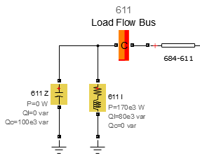
The figure shows examples of Load Flow Bus blocks set to define different phases of a given model, to perform an unbalanced load flow.

When the Configuration parameter is
set to on one side, the block
displays the block phase ports only on one side of the
block. You can connect the Load Flow Bus
block anywhere in the model to identify a connection line
as a load flow bus:

When the Configuration parameter is
set to on both sides, the block
displays the block phase ports on both sides of the block.
You can connect the Load Flow Bus block in
series with other Simscape
Electrical Specialized Power Systems blocks to identify
a connection line as a load flow bus.
Both options perform the same action, and you can seamlessly use either method to connect the Load Flow Bus blocks.
Dependencies
To enable this parameter, set
Connectors to
ABC,
AB,
AC,
BC,
A,
B, or
C.
Alphanumeric label. The Bus Identification label appears below the block as a block annotation.
Base voltage is usually the same as the nominal voltage of the load flow blocks connected to the Load Flow Bus block. The Base voltage values appears below the block as a block annotation.
Dependencies
To enable this parameter, set
Connectors to
single.
Required bus voltage magnitude, in pu. Depending on the bus type of the load flow blocks connected at that bus, this voltage corresponds to the swing bus voltage or the PV bus voltage.
Dependencies
To enable this parameter, set
Connectors to
single.
Swing bus voltage angle is used as a reference to compute voltage angles of all other buses in the model.
Dependencies
To enable this parameter, set
Connectors to
single.
Base voltage is usually the same as the nominal voltage of the load flow blocks connected to the Load Flow Bus block. The Base voltage values appears below the block as a block annotation.
Dependencies
To enable this parameter, set
Connectors to
single.
Specify the required bus voltage magnitude, in pu, for every phase specified by the Connectors parameter. Depending on the bus type of the load flow blocks connected at that bus, this voltage corresponds to the swing bus voltage or the PV bus voltage.
Dependencies
To enable this parameter, set
Connectors to
ABC,
AB,
AC,
BC,
A,
B, or
C.
Required bus voltage angle, in pu, for every phase specified by the Connectors parameter. The swing bus voltage angles are used as a reference to compute voltage angles of all other buses in the model.
Dependencies
To enable this parameter, set
Connectors to
ABC,
AB,
AC,
BC,
A,
B, or
C.
Load Flow
Bus voltage section
Displays the resulting bus voltage of phase A, in pu, once the load flow is solved. This parameter appears dimmed because it is updated by the Load Flow tool. The parameter value appears below the block as a block annotation.
The value is set to NaN by the Load
Flow tool when the load flow solution is not computed for
this phase (that is, when the
Connectors parameter is set to
BC,
B, or
C).
Displays the resulting bus voltage of phase B, in pu, once the load flow is solved. This parameter appears dimmed because it is updated by the Load Flow tool. The parameter value appears below the block as a block annotation.
The value is set to NaN by the Load
flow tool when the load flow solution is not computed for
this phase (that is, when the
Connectors parameter is set to
AC,
A, or
C).
Dependencies
To enable this parameter, set
Connectors to
ABC,
AB,
AC,
BC,
A,
B, or
C.
Displays the resulting bus voltage of phase C, in pu, once the load flow is solved. This parameter appears dimmed because it is updated by the Load Flow tool. The parameter value appears below the block as a block annotation.
The value is set to NaN by the Load
flow tool when the load flow solution is not computed for
this phase (that is, when the
Connectors parameter is set to
AB,
A, or
B).
Dependencies
To enable this parameter, set
Connectors to
ABC,
AB,
AC,
BC,
A,
B, or
C.
Bus angle section
Displays the resulting bus voltage angle of phase A, in pu, once the load flow is solved. This parameter appears dimmed because it is updated by the Load Flow tool. The parameter value appears below the block as a block annotation.
The value is set to NaN by the Load
Flow tool when the load flow solution is not computed for
this phase (that is, when the
Connectors parameter is set to
BC,
B, or
C).
Displays the resulting bus voltage angle of phase B, in pu, once the load flow is solved. This parameter appears dimmed because it is updated by the Load Flow tool. The parameter value appears below the block as a block annotation.
The value is set to NaN by the Load
flow tool when the load flow solution is not computed for
this phase (that is, when the
Connectors parameter is set to
AC,
A, or
C).
Dependencies
To enable this parameter, set
Connectors to
ABC,
AB,
AC,
BC,
A,
B, or
C.
Displays the resulting bus voltage angle of phase C, in pu, once the load flow is solved. This parameter appears dimmed because it is updated by the Load Flow tool. The parameter value appears below the block as a block annotation.
The value is set to NaN by the Load
flow tool when the load flow solution is not computed for
this phase (that is, when the
Connectors parameter is set to
AB,
A, or
B).
Dependencies
To enable this parameter, set
Connectors to
ABC,
AB,
AC,
BC,
A,
B, or
C.
Extended Capabilities
Version History
Introduced in R2011a