Reservoir (G)
R2026bBoundary conditions for gas network at constant or time-varying pressure and temperature
Reservoir (G) block

To add a block to a model, double-click the canvas and start typing the block name. Then, select the block from the list.
Libraries:
Simscape /
Foundation Library /
Gas /
Elements
Description
The Reservoir (G) block sets boundary conditions in a gas network. Port A, a gas conserving port, represents the reservoir inlet.
The volume of gas inside the reservoir is assumed infinite. Therefore, the flow is assumed quasi-steady.
Gas enters and leaves the reservoir at reservoir pressure, but its temperature is determined by the direction of gas flow. If the gas flows out of the reservoir, its temperature equals the reservoir temperature. The reservoir acts as a heat source. If the gas flows into the reservoir, its temperature is determined by the gas network upstream. The reservoir acts as a heat sink.
You specify the reservoir pressure and temperature with block parameter values or physical signals. The block provides a choice of two modeling options:
Static pressure and static temperature— To simplify the calculations, the block assumes that there is no difference between the pressure and temperature of gas inside the reservoir and at the exit port. This assumption is valid for applications with low-speed compressible flow, such as HVAC systems. You can also use it to simulate a portion of a system based on measured pressure and temperature at the boundary, that is, on the static pressure and static temperature.Total pressure and total temperature—This option assumes that the gas starts at rest and speeds up toward the exit port, which results in a reduction in pressure and temperature at the port. Use this modeling option for applications with high-speed compressible flows, such as aerospace, or for fluid dynamics analysis.Total pressure and total temperature are the pressure and temperature of gas at rest inside the reservoir. These quantities are also sometimes called stagnation pressure and temperature. They are related to the pressure and temperature at the reservoir port A by these equations
where:
ptotal is the total, or stagnation, pressure.
Ttotal is the total, or stagnation, temperature.
pA is the pressure at the reservoir port.
ToutA is the temperature at the reservoir port as the gas flows out of reservoir. If the gas flows into the reservoir, its temperature is determined by the gas network upstream.
h is the specific enthalpy.
s is the specific entropy.
is the mass flow rate of gas through the reservoir port. When the gas leaves the reservoir, is negative. The
minterm in the specific enthalpy equation assumes a value corresponding to the mass flow rate of gas when the gas leaves the reservoir. When the gas enters the reservoir, this term is 0.ρ is density.
SA is the cross-sectional area at the reservoir port.
This block also functions as a reference point for pressure and temperature measurements in a gas network. These measurements are relative to the reservoir static pressure and temperature, respectively. Connect the reservoir inlet to port B of a Pressure and Temperature Sensor (G) block to measure relative pressure and temperature of a node connected to the A port of the sensor.
Examples
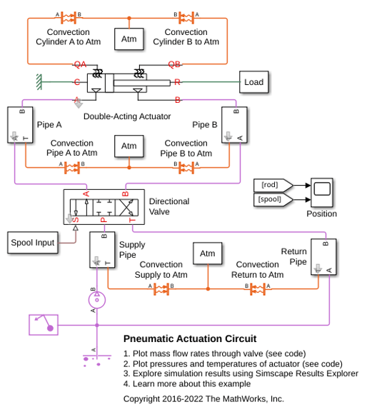
Pneumatic Actuation Circuit
How the Foundation Library gas components can be used to model a controlled pneumatic actuator. The Directional Valve is a masked subsystem created from Variable Local Restriction (G) blocks to model the opening and closing of the flow paths. The Double-Acting Actuator is a masked subsystem created from Translational Mechanical Converter (G) blocks to model the interface between the gas network and the mechanical translational network.
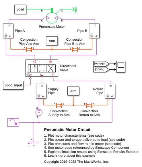
Pneumatic Motor Circuit
How a pneumatic vane motor can be modeled using the Simscape™ language. The Pneumatic Motor component is built using the Simscape Foundation gas domain. It inherits from the foundation.gas.two_port_steady base class, which contains common equations that implement the upwind energy flow rate and the gas properties at the ports. The Pneumatic Motor subclass implements equations that describe behaviors specific to the component, such as the motor torque and flow rate characteristics and the mass and energy balance. The Pneumatic Motor block is inserted into the model using the Simscape Component block without the need to generate a separate library.
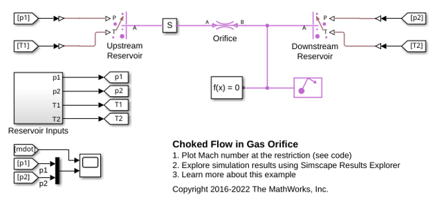
Choked Flow in Gas Orifice
The choking behavior of a gas orifice modeled by the Local Restriction (G) block. The Controlled Reservoir (G) blocks are used to set up controlled pressure and temperature boundary conditions from the Reservoir Inputs subsystem to test the gas orifice.

