RF Impairments for 5G NR Downlink Waveforms
This example shows how to generate a 5G new radio (NR) downlink waveform with full band allocation. This example also shows how to model RF impairments and compute and visualize the error vector magnitude (EVM) of the generated waveform. The generated waveform contains the physical downlink shared channel (PDSCH) channel and its associated DM-RS signal, and the physical downlink control channel (PDCCH).
Main Parameters
Use this suggested settings as a guide for setting up the parameters of the 5G Waveform as it provides information for subcarrier spacing, number of resource blocks as a function of bandwidth and subcarrier spacing as well as parameters for FR1 and FR2 carriers.
Suggested settings with transform precoding off for frequency range (FR1) (*)
BW(MHz) 5 10 15 20 25 30 40 50 60 80 90 100
NRB @15kHz 25 52 79 106 133 160 216 270
NRB @30kHz 11 24 38 51 65 78 106 133 162 217 245 273
NRB @60kHz 11 18 24 31 38 51 65 79 107 121 135
Suggested settings with transform precoding off for FR2 (*)
BW(MHz) 50 100 200 400
NRB @60kHz 66 128 264
NRB @120kHz 32 66 128 264
(*) Based on reference measurement channels from TS 38.101-1 and TS 38-101-2 Annex A2.3
Waveform and Carrier Configuration
Use the nrDLCarrierConfig object to configure the parameters needed for 5G NR downlink carrier waveform generation. This section sets parameters such as the subcarrier spacing (SCS), the cell ID, and the length of the generated waveform in subframes.
waveconfig = nrDLCarrierConfig;    % Create a downlink carrier configuration object
waveconfig.Label = 'DL carrier 1'; % Label for this downlink waveform configuration
waveconfig.NCellID = 0;            % Cell identity
waveconfig.ChannelBandwidth = 100; % Channel bandwidth (MHz)
waveconfig.FrequencyRange = 'FR2'; % 'FR1' or 'FR2'
waveconfig.NumSubframes = 1;       % Number of 1ms subframes in generated waveform
                                   % (1,2,4,8 slots per 1ms subframe, depending on SCS)
Define the SCS carrier using the maximum sizes for a 40 MHz NR channel. See TS 38.101-1 for more information on defined bandwidths and guard band requirements.
scscarrier = {nrSCSCarrierConfig};
scscarrier{1}.SubcarrierSpacing = 60;
scscarrier{1}.NSizeGrid = 128;
scscarrier{1}.NStartGrid = 0;
Bandwidth Parts
A BWP is formed by a set of contiguous resources sharing a numerology on a given carrier. This example can support the use of multiple BWPs using nrWavegenBWPConfig objects. For each BWP you can specify the subcarrier spacing (SCS), the cyclic prefix (CP) length, and the bandwidth. The SubcarrierSpacing parameter maps the BWP to the SCS carrier defined earlier. The NStartBWP parameter controls the location of the BWP in the carrier. Different BWPs can overlap each other.
% Set BWP configurations
bwp = {nrWavegenBWPConfig};
bwp{1}.BandwidthPartID = 1;                                 % BWP ID
bwp{1}.Label = 'BWP 1 @ 60 kHz';                            % Label for this BWP
bwp{1}.SubcarrierSpacing = scscarrier{1}.SubcarrierSpacing; % BWP subcarrier spacing
bwp{1}.CyclicPrefix = 'Normal';                             % BWP cyclic prefix for 60 kHz
bwp{1}.NSizeBWP = scscarrier{1}.NSizeGrid;                  % Size of BWP in PRBs
bwp{1}.NStartBWP = 0;                                       % Position of BWP, relative to point A, in CRBs
CORESET and Search Space Configuration
Specify the CORESET and the PDCCH search space configuration. The CORESET and search spaces specify the possible locations (in time and frequency) of the control channel transmissions for a given numerology.
% Define the CORESET and search configuration
coreset = {nrCORESETConfig};
searchspace = {nrSearchSpaceConfig};
PDCCH Instances Configuration
Specify the set of PDCCH transmission instances in the waveform by using a cell array.
pdcch = {nrWavegenPDCCHConfig};
PDSCH Instances Configuration
This section specifies the set of PDSCH instances in the waveform. You can set the following parameters for each instance:
Enable or disable this PDSCH sequence.
Specify the BWP carrying the PDSCH. The PDSCH uses the SCS specified for this BWP.
Power scaling in dB
Enable or disable the DL-SCH transport channel coding.
Transport block data source. You can use one of the following standard PN sequences:
'PN9-ITU', 'PN9', 'PN11', 'PN15', 'PN23'. You can specify the seed for the generator using a cell array in the form{'PN9', seed}. If no seed is specified, the generator is initialized with all ones.Target code rate used to calculate the transport block sizes.
Overhead parameter
Symbol modulation
Number of layers
Redundancy version (RV) sequence
pdsch = {nrWavegenPDSCHConfig};           % Create a PDSCH configuration object
pdsch{1}.Enable = 1;                      % Enable PDSCH sequence
pdsch{1}.Label = 'PDSCH 1';               % Label for this PDSCH sequence
pdsch{1}.BandwidthPartID = 1;             % Bandwidth part of PDSCH transmission
pdsch{1}.Power  = 0;                      % Power scaling in dB
pdsch{1}.Coding = 1;                      % Enable the DL-SCH transport channel coding
pdsch{1}.DataSource = 'PN9';              % Channel data source
pdsch{1}.TargetCodeRate = 0.4785;         % Code rate used to calculate transport block sizes
pdsch{1}.XOverhead = 0;                   % Rate matching overhead
pdsch{1}.Modulation = '64QAM';            % 'QPSK', '16QAM', '64QAM', '256QAM'
pdsch{1}.NumLayers = 1;                   % Number of PDSCH layers
pdsch{1}.RVSequence = 0;                  % RV sequence to be applied cyclically across the PDSCH allocation sequence
Allocation
The following diagram represents some of the parameters used in the PDSCH allocation.
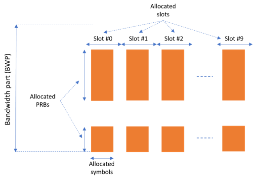
You can set the following parameters to control the PDSCH allocation. Note that these parameters are relative to the BWP.
Symbols in a slot allocated to each PDSCH instance.
Slots in a frame used for the sequence of PDSCH.
Period of the allocation in slots. If this is empty it indicates no repetition.
PRB allocation, which is relative to the BWP.
RNTI. This value is used to link the PDSCH to an instance of the PDCCH.
NID for scrambling the PDSCH bits.
pdsch{1}.SymbolAllocation = [0 14];            % First symbol and length
pdsch{1}.SlotAllocation = 0;                   % Allocated slot indices for PDSCH sequence
pdsch{1}.Period = 1;                           % Allocation period in slots
pdsch{1}.PRBSet = 0:scscarrier{1}.NSizeGrid-1; % PRB allocation
pdsch{1}.RNTI = 0;                             % RNTI
pdsch{1}.NID = 1;                              % Scrambling for data part
pdsch{1}.ReservedCORESET = 1;                  % Rate matching pattern, defined by CORESET IDs
PDSCH DM-RS Configuration
Set the DM-RS parameters.
% Antenna port and DM-RS configuration (TS 38.211 section 7.4.1.1)
pdsch{1}.MappingType = 'A';                % PDSCH mapping type ('A'(slot-wise),'B'(non slot-wise))
pdsch{1}.DMRSPower = 0;                    % Additional power boosting in dB
pdsch{1}.DMRS.DMRSConfigurationType = 2;   % DM-RS configuration type (1,2)
pdsch{1}.DMRS.NumCDMGroupsWithoutData = 1; % Number of DM-RS CDM groups without data. The value can be one of the set {1,2,3}
pdsch{1}.DMRS.DMRSPortSet = [];            % DM-RS antenna ports used ([] gives port numbers 0:NumLayers-1)
pdsch{1}.DMRS.DMRSTypeAPosition = 2;       % Mapping type A only. First DM-RS symbol position (2,3)
pdsch{1}.DMRS.DMRSLength = 1;              % Number of front-loaded DM-RS symbols (1(single symbol),2(double symbol))
pdsch{1}.DMRS.DMRSAdditionalPosition = 0;  % Additional DM-RS symbol positions (max range 0...3)
pdsch{1}.DMRS.NIDNSCID = 1;                % Scrambling identity (0...65535)
pdsch{1}.DMRS.NSCID = 0;                   % Scrambling initialization (0,1)
Waveform Generation
Assign all the channel and signal parameters into the main carrier configuration object, nrDLCarrierConfig, then generate and plot the waveform.
waveconfig.SCSCarriers = scscarrier;
waveconfig.BandwidthParts = bwp;
waveconfig.CORESET = coreset;
waveconfig.SearchSpaces = searchspace;
waveconfig.PDCCH = pdcch;
waveconfig.PDSCH = pdsch;
waveconfig.SSBurst.Enable = 0; % Disable SS Burst

% Generate complex baseband waveform
[waveform,info] = nrWaveformGenerator(waveconfig);
The nrWaveformGenerator function returns the time domain waveform and a structure array, info, which contains the following information:
The resource grid corresponding to this BWP
The resource grid of the overall bandwidth containing the channels and signals in this BWP
An info structure with information corresponding to the BWP. The contents of this info structure for the selected BWP are shown below.
Information regarding the control and data channels
disp('Information associated to BWP 1:')
disp(info.ResourceGrids.Info)
Information associated to BWP 1:
                   Nfft: 2048
             SampleRate: 122880000
    CyclicPrefixLengths: [208 144 144 144 144 144 144 144 144 … ] (1×56 double)
          SymbolLengths: [2256 2192 2192 2192 2192 2192 2192 … ] (1×56 double)
              Windowing: 0
           SymbolPhases: [0 0 0 0 0 0 0 0 0 0 0 0 0 0 0 0 0 0 … ] (1×56 double)
         SymbolsPerSlot: 14
       SlotsPerSubframe: 4
          SlotsPerFrame: 40
                     k0: 0
Perform Filtering of Waveform to Improve ACLR
The waveform generated may have out-of-band spectral emissions owing to the implicit rectangular pulse shaping in the OFDM modulation (each OFDM subcarrier has a sinc shape in the frequency domain). In order to achieve a better adjacent channel leakage ratio (ACLR) performance, you can apply filtering to the waveform. Design a filter with a transition band that starts at the edge of the occupied transmission bandwidth and stops at the edge of the overall channel bandwidth. This filter involves no rate change: it just shapes the spectrum within the original bandwidth of the waveform. The filter is first designed, then applied to the waveform.
% Design filter
fir = dsp.LowpassFilter();
fir.SampleRate = info.ResourceGrids.Info.SampleRate;
BW = scscarrier{1}.SubcarrierSpacing * scscarrier{1}.NSizeGrid * 12 * 1e3;
fir.PassbandFrequency = BW/2;
fir.StopbandFrequency = (BW/2)*1.03;
fir.StopbandAttenuation = 80;   % dB

% Apply filter
waveform = [waveform; zeros(200,size(waveform,2))];
txWaveform = step(fir,waveform);
infoFIR = cost(fir);

% Account for filter delay
filDelay = floor(infoFIR.NumCoefficients/2);
txWaveform = [txWaveform(filDelay+1:end,:); zeros(filDelay,size(txWaveform,2))];

% Generate timeseries 5G Signal
OSR = 4;
waveformUp = resample(txWaveform,OSR,1);
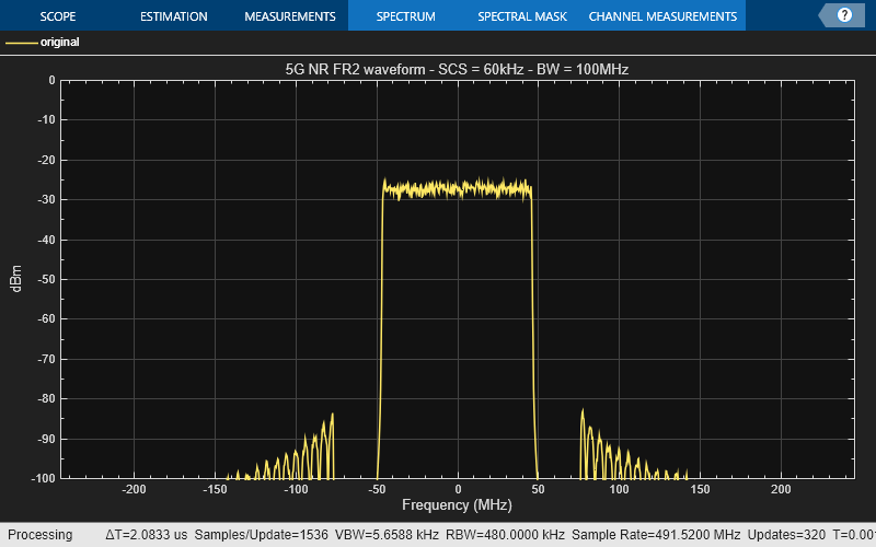
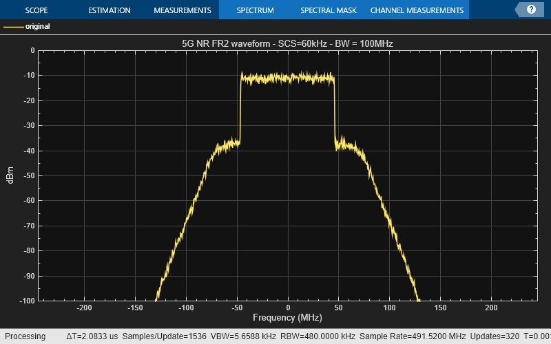
Spectral Response of Generated Waveform
Plot the spectral response of generated waveform.
Title = sprintf('5G NR %s waveform - SCS = %dkHz - BW = %dMHz', ...
    waveconfig.FrequencyRange,...
    scscarrier{1}.SubcarrierSpacing,waveconfig.ChannelBandwidth);
sp = spectrumAnalyzer('SampleRate', fir.SampleRate*OSR,...
    'ViewType','Spectrum',...
    'ShowLegend',true,'ChannelNames',{'original' 'filtered'},...
    'YLimits',[-100 0], 'Title',Title,'Method','welch','AveragingMethod','exponential');
sp(waveformUp);
Create RF Transmitter with Impairments
Build a cascade of RF elements with impairments.
elements(1) = modulator(Gain=8,NF=5.8,OIP2=41,OIP3=29,LO=28e9);
elements(2) = amplifier(Gain=12,NF=3,OIP3=26);
elements(3) = rffilter('FilterType','Chebyshev','ResponseType','Bandpass','Implementation','Transfer function','FilterOrder',5,'PassbandAttenuation',60e-3, ...
    'PassbandFrequency',[27.92 28.08]*1e9, ...
    'Zin',50, ...
    'Zout',50, ...
    'Name','Filter');
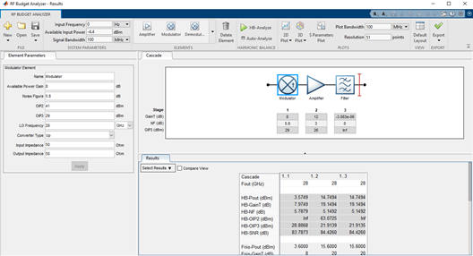
Construct an rfbudget object to perform RF budget analysis.
b = rfbudget(Elements=elements,InputFrequency=0,AvailableInputPower=-4.4,SignalBandwidth=100e6,Solver='HarmonicBalance',AutoUpdate=1);
Type show(b) at the command line to visualize the transmitter in the RF Budget Analyzer app.
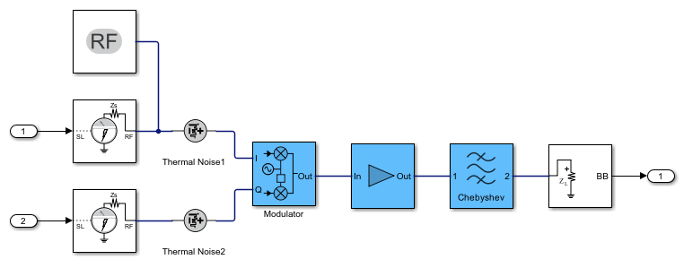
Create RF Model for Simulation
Create an RF model from the RF budget object for circuit envelope simulation.
rfs_mmW_FR2 = rfsystem(b,'ModelName','mmW_FR2_Tx');
rfs_mmW_FR2.SampleTime = 1/fir.SampleRate/OSR;
open_system(rfs_mmW_FR2);
Add the Tx front end impairments to the NR waveform.
rxWaveformUp = rfs_mmW_FR2(real(waveformUp),imag(waveformUp));
release(rfs_mmW_FR2);
Display the 5G NR waveform.
Title = sprintf('5G NR %s waveform - SCS=%dkHz - BW = %dMHz', ...
    waveconfig.FrequencyRange,...
    scscarrier{1}.SubcarrierSpacing,waveconfig.ChannelBandwidth);
sp = spectrumAnalyzer('SampleRate', fir.SampleRate*OSR,...
    'ViewType','Spectrum',...
    'ShowLegend',true,'ChannelNames',{'original' 'filtered'},...
    'YLimits',[-100 0], 'Title',Title,'Method','welch','AveragingMethod','exponential');
sp(rxWaveformUp);
Downconversion
Downconvert the receiver waveform using the dsp.FIRDecimator object.
nr_fir_dec = dsp.FIRDecimator('DecimationFactor',OSR);
rxWaveform = nr_fir_dec(rxWaveformUp);
release(nr_fir_dec);
Synchronization
Estimate the timing offset.
carrier = nrCarrierConfig;
carrier.NCellID = waveconfig.NCellID;
carrier.NSizeGrid = waveconfig.SCSCarriers{1}.NSizeGrid;
carrier.SubcarrierSpacing = waveconfig.SCSCarriers{1}.SubcarrierSpacing;
carrier.CyclicPrefix = waveconfig.BandwidthParts{1}.CyclicPrefix;
[offset,mag] = nrTimingEstimate(carrier,rxWaveform,info.ResourceGrids.ResourceGridBWP);
waveformSync = rxWaveform(1+offset:end,:);
Demodulation
Demodulate the multi-antenna time domain waveform to return the received resource element array.
rxGrid = nrOFDMDemodulate(carrier, waveformSync);
NrSlot = floor(size(rxGrid,2)/info.ResourceGrids.Info.SymbolsPerSlot);
Channel Estimation and Equalization for Each Slot
Get the allocated slots and OFDM symbols per slot.
allocatedSlots = zeros(1,NrSlot);
for i=1:length(allocatedSlots)
    allocatedSlots(i) = info.WaveformResources.PDSCH.Resources(i).NSlot;
end
L = carrier.SymbolsPerSlot; % OFDM symbols per slot

% Perform channel estimation to detect the distorted transmitted signal.
for NSlot = 1:length(allocatedSlots)
    % Grid for current slot
    SlotID = allocatedSlots(NSlot);
    rxSlot = rxGrid(:,(1:L)+(SlotID*L),:);
    refSlot = info.ResourceGrids.ResourceGridBWP(:,(1:L)+(SlotID*L),:);

    % Perform channel estimation
    estChannelGrid = nrChannelEstimate(carrier,rxSlot,refSlot);

    % Get PDSCH resource elements from the received grid
    pdschIndices = info.WaveformResources.PDSCH.Resources(NSlot).ChannelIndices;
    [pdschRx,pdschHest] = nrExtractResources(pdschIndices,rxSlot,estChannelGrid);

    % Equalize the signal to remove co-channel interference
    noiseEst = 0;    % Set noise to 0 for zero-forcing equalization
    [pdschEq,csi] = nrEqualizeMMSE(pdschRx,pdschHest,noiseEst);

    % Perform layer demapping, symbol demodulation, and descrambling
    modulation = waveconfig.PDSCH{1}.Modulation;
    RNTI = waveconfig.PDSCH{1}.RNTI;
    [dlschLLRs,rxSymbols] = nrPDSCHDecode(pdschEq,modulation,...
        carrier.NCellID,RNTI,noiseEst);
    rxSymbols = rxSymbols{1};
Compute EVM
Compute the EVM on the resulting waveform to determine the impact of the impairments. Set modulation order.
    M = modOrder(modulation);
    % Demodulate
    refBits = qamdemod(rxSymbols,M,'UnitAveragePower',true);
    % Remodulate to produce reference symbols
    refSym = qammod(refBits,M,'UnitAveragePower',true);
    evm = comm.EVM;
    rmsEVM = evm(rxSymbols,refSym);
    fprintf('slot %d: EVM = %.3f%% (%.1f dB)\n', NSlot-1, rmsEVM, 20*log10(rmsEVM/100));
slot 1: EVM = 5.082% (-25.9 dB)
slot 2: EVM = 5.132% (-25.8 dB)
slot 3: EVM = 5.309% (-25.5 dB)
end
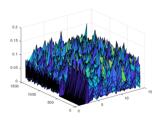
Visualize EVM in 3-D Plot
Visualize EVM of the last slot in a 3-D plot along with the 2-D constellation plot.
x = zeros(size(rxSlot));
x(pdschIndices) = abs(rxSymbols-refSym);
surf(abs(x))
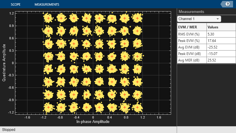
Visualize the constellation diagram.
refC = qammod(0:2^log2(M)-1,2^log2(M))/6*.925;
constDiagram = comm.ConstellationDiagram('ReferenceConstellation',refC,...
    'XLimits',[-1 1],'YLimits',[-1.25 1.25],...
    'EnableMeasurements',1,'Position',[1000,250, 800,450]);
constDiagram(rxSymbols);
release(constDiagram);
Local Function
function M = modOrder(Modulation)
    % This function maps the modulation scheme to a QAM modulation order
    switch Modulation
        case 'QPSK'
            M=4;
        case '16QAM'
            M=16;
        case '64QAM'
            M=64;
        otherwise
            M=256;
    end
end
slot 0: EVM = 5.065% (-25.9 dB)