Map Network Parameters to Modeling Frequencies
In a physical system, each block provides network parameters at different frequencies. These frequencies are not necessarily the modeling frequencies for the physical system in which the block resides. To create a baseband-equivalent model, RF Blockset™ Equivalent Baseband software must calculate the values of the S-parameters at the modeling frequencies.
Individual physical blocks calculate the S-parameters at the modeling frequencies determined by the Input Port block parameters. Each block interpolates its S-parameters to determine the S-parameters at the modeling frequencies. If the block contains network Y- or Z-parameters, it first converts them to S-parameters.
Specifically, the block orders the S-parameters in the ascending
order of their frequencies, fn.
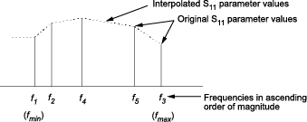
Then, it interpolates the S-parameters using the MATLAB® interp1 function. For example, the curve
in the following diagram illustrates the result of interpolating the
S11 parameters at original frequencies f1 through f5.
The Interpolation method field in the individual
block dialog boxes enables you to specify the interpolation method
as Cubic, Linear (default),
or Spline. For more information about these methods,
see the interp1 reference page
in the MATLAB documentation.
As shown in the previous diagram, each block uses the parameter values at fmin for all modeling frequencies smaller than fmin. The block uses the parameter values at fmax for all modeling frequencies greater than fmax. In both cases, the results may not be accurate, so you need to specify network parameter values over a range of frequencies that is wide enough to account for the block behavior.