pattern
System object: phased.IsotropicProjector
Namespace: phased
Plot isotropic projector directivity and patterns
Syntax
pattern(projector,FREQ)
pattern(projector,FREQ,AZ)
pattern(projector,FREQ,AZ,EL)
pattern(___,Name,Value)
[PAT,AZ_ANG,EL_ANG] = pattern(___)
Description
pattern(
plots
the 3D directivity pattern (in dBi) for the projector specified in projector
,FREQ
)projector
.
The operating frequency is specified in FREQ
.
pattern(
plots
the projector directivity pattern at the specified azimuth angle.projector
,FREQ
,AZ
)
pattern(
plots
the projector directivity pattern at specified azimuth and elevation
angles.projector
,FREQ
,AZ
,EL
)
pattern(___,
plots
the projector pattern with additional options specified by one or
more Name,Value
)Name,Value
pair arguments.
returns the projector pattern in [PAT,AZ_ANG,EL_ANG]
= pattern(___)PAT
. The AZ_ANG
output
contains the coordinate values corresponding to the rows of PAT
.
The EL_ANG
output contains the coordinate values
corresponding to the columns of PAT
. If the 'CoordinateSystem'
parameter
is set to 'uv'
, then AZ_ANG
contains
the U coordinates of the pattern and EL_ANG
contains
the V coordinates of the pattern. Otherwise, they
are in angular units in degrees. UV units are dimensionless.
Input Arguments
FREQ
— Frequency for computing directivity and patterns
positive scalar | 1-by-L real-valued row vector
Frequencies for computing directivity and patterns, specified as a positive scalar or 1-by-L real-valued row vector. Frequency units are in hertz.
For an antenna, microphone, or sonar hydrophone or projector element,
FREQ
must lie within the range of values specified by theFrequencyRange
orFrequencyVector
property of the element. Otherwise, the element produces no response and the directivity is returned as–Inf
. Most elements use theFrequencyRange
property except forphased.CustomAntennaElement
andphased.CustomMicrophoneElement
, which use theFrequencyVector
property.For an array of elements,
FREQ
must lie within the frequency range of the elements that make up the array. Otherwise, the array produces no response and the directivity is returned as–Inf
.
Example: [1e8 2e6]
Data Types: double
AZ
— Azimuth angles
[-180:180]
(default) | 1-by-N real-valued row vector
Azimuth angles for computing directivity and pattern, specified as a 1-by-N real-valued row vector where N is the number of azimuth angles. Angle units are in degrees. Azimuth angles must lie between –180° and 180°.
The azimuth angle is the angle between the x-axis and the projection of the direction vector onto the xy plane. When measured from the x-axis toward the y-axis, this angle is positive.
Example: [-45:2:45]
Data Types: double
EL
— Elevation angles
[-90:90]
(default) | 1-by-M real-valued row vector
Elevation angles for computing directivity and pattern, specified as a 1-by-M real-valued row vector where M is the number of desired elevation directions. Angle units are in degrees. The elevation angle must lie between –90° and 90°.
The elevation angle is the angle between the direction vector and xy-plane. The elevation angle is positive when measured towards the z-axis.
Example: [-75:1:70]
Data Types: double
Name-Value Arguments
Specify optional pairs of arguments as
Name1=Value1,...,NameN=ValueN
, where Name
is
the argument name and Value
is the corresponding value.
Name-value arguments must appear after other arguments, but the order of the
pairs does not matter.
Before R2021a, use commas to separate each name and value, and enclose
Name
in quotes.
CoordinateSystem
— Plotting coordinate system
'polar'
(default) | 'rectangular'
| 'uv'
Plotting coordinate system of the pattern, specified as the
comma-separated pair consisting of 'CoordinateSystem'
and
one of 'polar'
, 'rectangular'
,
or 'uv'
. When 'CoordinateSystem'
is
set to 'polar'
or 'rectangular'
,
the AZ
and EL
arguments
specify the pattern azimuth and elevation, respectively. AZ
values
must lie between –180° and 180°. EL
values
must lie between –90° and 90°. If 'CoordinateSystem'
is
set to 'uv'
, AZ
and EL
then
specify U and V coordinates,
respectively. AZ
and EL
must
lie between -1 and 1.
Example: 'uv'
Data Types: char
Type
— Displayed pattern type
'directivity'
(default) | 'efield'
| 'power'
| 'powerdb'
Displayed pattern type, specified as the comma-separated pair
consisting of 'Type'
and one of
'directivity'
— directivity pattern measured in dBi.'efield'
— field pattern of the sensor or array. For acoustic sensors, the displayed pattern is for the scalar sound field.'power'
— power pattern of the sensor or array defined as the square of the field pattern.'powerdb'
— power pattern converted to dB.
Example: 'powerdb'
Data Types: char
Normalize
— Display normalize pattern
true
(default) | false
Display normalized pattern, specified as the comma-separated pair consisting of
'Normalize
' and a Boolean. Set this parameter to
true
to display a normalized pattern. This parameter does not
apply when you set 'Type'
to 'directivity'
.
Directivity patterns are already normalized.
Data Types: logical
PlotStyle
— Plotting style
'overlay'
(default) | 'waterfall'
Polarization
— Polarized field component
'combined'
(default) | 'H'
| 'V'
Polarized field component to display, specified as the comma-separated pair consisting of
'Polarization' and 'combined'
, 'H'
, or
'V'
. This parameter applies only when the sensors are
polarization-capable and when the 'Type'
parameter is not set to
'directivity'
. This table shows the meaning of the display
options.
'Polarization' | Display |
---|---|
'combined' | Combined H and V polarization components |
'H' | H polarization component |
'V' | V polarization component |
Example: 'V'
Data Types: char
Output Arguments
PAT
— Element pattern
N-by-M real-valued matrix
Examples
Response and Pattern of Isotropic Projector at Single Frequency
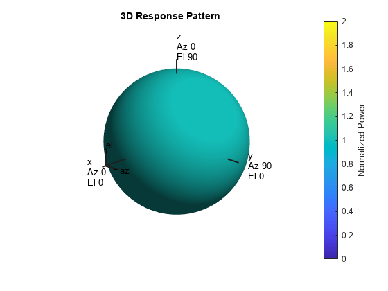
Examine the response and patterns of an isotropic projector operating between 1 kHz and 10 kHz.
Set the projector parameters and obtain the voltage response at five different elevation angles: -30°, -15°, 0°, 15° and 30°. All elevation angles at 0° azimuth angle. The voltage response is computed at 2 kHz.
projector = phased.IsotropicProjector('FrequencyRange',[1,10]*1e3);
fc = 2e3;
resp = projector(fc,[0,0,0,0,0;-30,-15,0,15,30]);
Draw a 3-D plot of the voltage response.
pattern(projector,fc,[-180:180],[-90:90],'CoordinateSystem','polar', ... 'Type','power')
Response and Pattern of Isotropic Projector at Multiple Frequencies
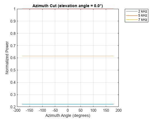
Examine the response and patterns of an isotropic projector at three different frequencies. The projector operates between 1 kHz and 10 kHz. Specify the voltage response as a vector.
Set up the projector parameters, and obtain the voltage response at 45° azimuth and 30° elevation. Compute the responses at signal frequencies of 2, 5, and 7 kHz.
projector = phased.IsotropicProjector('FrequencyRange',[1 10]*1e3, ... 'VoltageResponse',[90 95 100 95 90]); fc = [2e3 5e3 7e3]; resp = projector(fc,[45;30]); resp
resp = 1×3
0.0426 0.0903 0.0708
Next, draw a 2-D plot of the voltage response as a function of azimuth.
pattern(projector,fc,[-180:180],0,'CoordinateSystem','rectangular', ... 'Type','power')
More About
Directivity
Directivity describes the directionality of the radiation pattern of a sensor element or array of sensor elements.
Higher directivity is desired when you want to transmit more radiation in a specific direction. Directivity is the ratio of the transmitted radiant intensity in a specified direction to the radiant intensity transmitted by an isotropic radiator with the same total transmitted power
where Urad(θ,φ) is the radiant intensity of a transmitter in the direction (θ,φ) and Ptotal is the total power transmitted by an isotropic radiator. For a receiving element or array, directivity measures the sensitivity toward radiation arriving from a specific direction. The principle of reciprocity shows that the directivity of an element or array used for reception equals the directivity of the same element or array used for transmission. When converted to decibels, the directivity is denoted as dBi. For information on directivity, read the notes on Element Directivity and Array Directivity.
Version History
Introduced in R2017a
See Also
MATLAB コマンド
次の MATLAB コマンドに対応するリンクがクリックされました。
コマンドを MATLAB コマンド ウィンドウに入力して実行してください。Web ブラウザーは MATLAB コマンドをサポートしていません。
Select a Web Site
Choose a web site to get translated content where available and see local events and offers. Based on your location, we recommend that you select: .
You can also select a web site from the following list:
How to Get Best Site Performance
Select the China site (in Chinese or English) for best site performance. Other MathWorks country sites are not optimized for visits from your location.
Americas
- América Latina (Español)
- Canada (English)
- United States (English)
Europe
- Belgium (English)
- Denmark (English)
- Deutschland (Deutsch)
- España (Español)
- Finland (English)
- France (Français)
- Ireland (English)
- Italia (Italiano)
- Luxembourg (English)
- Netherlands (English)
- Norway (English)
- Österreich (Deutsch)
- Portugal (English)
- Sweden (English)
- Switzerland
- United Kingdom (English)