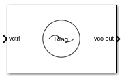
Ring Oscillator VCO
Model ring oscillator VCO
Libraries:
Mixed-Signal Blockset /
PLL /
Building Blocks
Description
The Ring Oscillator VCO block models the output signal, frequency control, period jitter, and flicker noise of a VCO (voltage controlled oscillator) such as a bias controlled ring oscillator circuit. This block generates the phase noise using a mathematical description of the phase noise of ring oscillators. This allows faster computation of simulation results during both startup and the subsequent simulations. You can also control the phase noise profile by selecting the Gaussian noise level, corner frequency, and flicker exponent. The phase noise spectrum is limited to the spectra that can be produced by the physical model of a ring oscillator.
You can choose the coefficients for the mathematical description of the phase noise. You can provide a specific phase noise spectral density from a data sheet and compare that to the phase noise spectral density that the mathematical coefficients produce. You can then adjust the coefficients to fit the specified phase noise in a way that makes the most sense physically.
Note
If the flicker noise corner frequency is set to zero, the Ring Oscillator VCO block can also be used to model a tank-tuned VCO.
Examples
This example shows how to validate the phase noise profile of a VCO device under test (DUT) using a VCO Testbench.
Open the model ringOscVCOPhaseNoise. The model consists of a Ring Oscillator VCO block and a VCO Testbench.
model = 'ringOscVCOPhaseNoise';
open_system(model)

close_system(model)
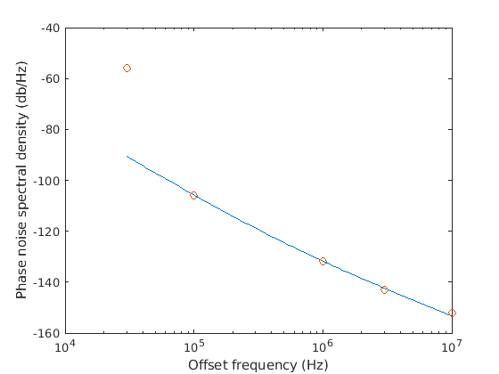
The voltage sensitivity of the VCO is set to 1.25e6 Hz, and the free running frequency is 2e9 Hz. Check that Add phase noise parameter is enabled. Click the Estimate phase noise parameters button, then click Plot fit to see how the phase noise is fitted against the specification. In the attached model, the fit is good.
The testbencch is set to measure the Phase noise metric of the VCO in the Measurement option. The Control voltage provided to the input of VCO is 4 V. So, the VCO operates at 2.5 GHz frequency. Click the Autofill setup parameters button to automatically calculate the Resolution bandwidth (Hz), and No. of spectral averages. Click the Autofill target metric button to automatically import the phase noise target profile to the VCO Testbench.
Run simulation for 8e-4 s, as recommended in the Block Parameters dialog box.
sim(model);
open_system([model '/VCO Testbench'])

Double click the VCO Testbench block to open the Block Parameters dialog box. Click on the Plot measurement button.

The operating frequency matches the predicted frequency 2.5 GHz. The measured phase noise profile also matches the target profile.
Ports
Input
Output
Parameters
More About
The Ring Oscillator VCO block generates the phase noise with the help of a Gaussian noise source and a flicker filter.
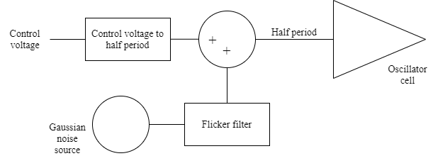
When enable the phase noise, the phase noise is calculated from the variance of the period offset stochastic process from the spectral density at a single frequency. Given the oscillation frequency f0, offset frequency f , and single sideband spectral density ℒ(f) , the variance of the period offset is:
Thus, except for flicker noise, you need a period offset derived from an uncorrelated random process with a constant variance. This period offset is generated by the block’s Gaussian noise source.
To model flicker noise, the flicker filter introduces additional gain at low frequencies, down to four orders of magnitude below the flicker corner frequency. To increase the energy spectral density from 1/f2 to 1/f3, the flicker filter must introduce a voltage gain of 1/√f below the corner frequency while maintaining unity gain above the corner frequency. To achieve this, the flicker filter is a recursive digital filter with an alternating sequence of four poles and four zeros. The lowest frequency zero is a constant factor higher than the lowest frequency pole, the next higher frequency pole is the same constant factor higher than the lowest frequency zero, and that pattern of alternating poles and zeros is maintained through the remainder of the sequence. The constant factor is a function of the flicker filter exponent, with a factor of the square root of ten for the nominal case of 1/f flicker noise.
To minimize numerical noise in the flicker filter, the sample rate of the Gaussian noise source and flicker filter is limited to 20 times the highest phase noise specification offset frequency, unless that sample rate is comparable to or greater than twice the frequency of oscillation. For higher phase specification noise offset frequencies, the sample rate is limited to twice the frequency of oscillation.
The variance of the Gaussian noise source is adjusted to compensate for the difference in sample rate between the noise source and the oscillator’s frequency of oscillation.
When the phase noise is disabled, the variance of the Gaussian noise is set to zero.
Specified phase noise spectra often include measurement artifacts that should not be included in the model of the VCO itself. While the parameter values produced by the Estimate phase noise parameters button will often come close to creating an appropriate physical model, there will be cases that require your judgement. Two common problems are noise floor and resolution bandwidth.
Sometimes, the measured phase noise appears to match a physical model up to frequencies for which the phase noise may be below the noise floor of the measurement.

It appears that there is a measurement noise floor at –140 dBc/Hz for the specification dataset, and the phase noise for the device under test is probably below that noise floor for offset frequencies above 100 MHz. In this case, a set of parameter values that fit best to the data at lower frequency offsets is likely to produce a more accurate model.
Sometimes, the measured phase noise appears to match a physical model at all levels except the lowest frequency offset.
The most likely cause for a result such as this is that the resolution bandwidth used to make the measurement was too large to produce an accurate measurement at the lowest frequency offset, 30 kHz in this case. Even if the carrier was outside the passband of the measurement filter, the carrier energy passed through the limited stopband rejection of the measurement filter was much larger than the energy in the passband. In this case, a set of parameter values that fit best to the data at higher frequency offsets is likely to produce a more accurate model.