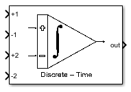
DT Integrator
Libraries:
Mixed-Signal Blockset /
ADC /
Building Blocks
Description
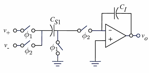
Use the DT Integrator block to perform true discrete-time integration of the voltage difference between the input ports. It is used for behavioral modeling of switched‑capacitor delta-sigma (ΔΣ) modulators. The block operates in the discrete‑time domain and implements integration using either a Forward Euler (FE) or Lossless‑Direct (LD) solver, closely matching the behavior of practical SC integrators.
The integrator supports 1 to 4 branched inputs, allowing straightforward realization of feedforward and feedback summation paths commonly found in delta-sigma loop filters. Its internal operation is based on charge‑transfer principles, rather than ideal mathematical integration, enabling accurate modeling of real switched‑capacitor architectures.
To support realistic system‑level simulation, the block includes a range of circuit‑level non‑idealities, such as finite op‑amp gain and bandwidth, sampling delay, capacitor mismatch, and clock‑phase timing effects. These non-idealities make the block particularly suitable for evaluating stability, noise‑shaping performance, and robustness of ΔΣ modulators prior to circuit‑level implementation.
Ports
Input
Input signal at the non-inverting input port at branch 1, specified as a scalar.
Data Types: double
Input signal at the inverting input port at branch 1, specified as a scalar.
Data Types: double
Input signal at the non-inverting input port at branch 2, specified as a scalar.
Dependencies
To enable this port, set Number of branch to
2 or higher.
Data Types: double
Input signal at the inverting input port at branch 2, specified as a scalar.
Dependencies
To enable this port, set Number of branch to
2 or higher.
Data Types: double
Input signal at the non-inverting input port at branch 3, specified as a scalar.
Dependencies
To enable this port, set Number of branch to
3 or higher.
Data Types: double
Input signal at the inverting input port at branch 3, specified as a scalar.
Dependencies
To enable this port, set Number of branch to
3 or higher.
Data Types: double
Input signal at the non-inverting input port at branch 4, specified as a scalar.
Dependencies
To enable this port, set Number of branch to
4.
Data Types: double
Input signal at the inverting input port at branch 4, specified as a scalar.
Dependencies
To enable this port, set Number of branch to
4.
Data Types: double
Output
Integrated output signal, returned as a scalar.
Data Types: double
Parameters
To edit block parameters interactively, use the Property Inspector. From the Simulink® Toolstrip, on the Simulation tab, in the Prepare gallery, select Property Inspector.
Solver type for the integrator model, specified as one of the following:
Forward - Euler— This method approximates the integral by assuming that the input remains constant at the beginning of the sampling interval. This method finds the solution by stepping forward in small increments. It is easy to implement but can be unstable for stiff equations or large time steps. This method is suitable for simple systems where stability is not a major concern. It is typically used for basic numerical simulations, simple DSP demonstrations, and educational examples.Lossless - Direct— This method uses a middle-point integrator that approximates the integral using the input value at the center of the interval. This symmetry makes the method lossless in phase. This method offers excellent frequency-domain accuracy and preserves the sinusoidal waveforms. But the stability is not guaranteed and it is not suitable for standalone robust filter designs. It is usually used for switched‑capacitor filter analysis, signal modeling and theory, and lossless integrator structures.
Programmatic Use
Block parameter:
SolverType |
| Type: character vector |
Values:
Forward - Euler | Lossless -
Direct |
Default:
Forward - Euler |
Number of integrator branches, specified as 1,
2, 3, or 4.
Programmatic Use
Block parameter:
NumberOfBranches |
| Type: character vector |
Values:
1 | 2 | 3 |
4 |
Default:
2 |
Clock period to use to sample the input signal, specified as a positive real scalar.
Programmatic Use
Block parameter:
SampleTime |
| Type: character vector |
| Values: positive real scalar |
Default:
1/5.12e6 |
Select this parameter to enable nonlinear incomplete settling error. By default, this option is selected.
Programmatic Use
Block parameter:
EnableSettling |
| Type: character vector |
Values:
off | on |
Default:
on |
Capacitor
Capacitance of integration capacitor in F, specified as a nonnegative real scalar.
Programmatic Use
Block parameter:
Ci |
| Type: character vector |
| Values: nonnegative real scalar |
Default:
24e-12 |
Capacitance of sampling capacitor at branch 1 in F, specified as a nonnegative real scalar.
Programmatic Use
Block parameter:
Csb1 |
| Type: character vector |
| Values: nonnegative real scalar |
Default:
6e-12 |
Capacitance of sampling capacitor at branch 2 in F, specified as a nonnegative real scalar.
Dependencies
To enable this parameter, set Number of branch to
2.
Programmatic Use
Block parameter:
Csb2 |
| Type: character vector |
| Values: nonnegative real scalar |
Default:
6e-12 |
Capacitance of sampling capacitor at branch 3 in F, specified as a nonnegative real scalar.
Dependencies
To enable this parameter, set Number of branch to
3.
Programmatic Use
Block parameter:
Csb3 |
| Type: character vector |
| Values: nonnegative real scalar |
Default:
6e-12 |
Capacitance of sampling capacitor at branch 4 in F, specified as a nonnegative real scalar.
Dependencies
To enable this parameter, set Number of branch to
4.
Programmatic Use
Block parameter:
Csb4 |
| Type: character vector |
| Values: nonnegative real scalar |
Default:
6e-12 |
Capacitance of load capacitor in F, specified as a positive real scalar.
Programmatic Use
Block parameter:
Cload |
| Type: character vector |
| Values: positive real scalar |
Default:
2.28e-12 |
Select this parameter to enable the effects of capacitor nonlinearity. By default, this option is deselected.
Programmatic Use
Block parameter:
EnableCapacitorNonlinearity |
| Type: character vector |
Values:
off | on |
Default:
off |
First-order coefficient for capacitor nonlinearity, specified as a nonnegative real scalar.
Dependencies
To enable this parameter, select Enable capacitor non-linearity in the Capacitor tab.
Programmatic Use
Block parameter:
CapacitorFirstOrderNonlinearity |
| Type: character vector |
| Values: nonnegative real scalar |
Default:
0 |
Second-order coefficient for capacitor nonlinearity, specified as a nonnegative real scalar.
Dependencies
To enable this parameter, select Enable capacitor non-linearity in the Capacitor tab.
Programmatic Use
Block parameter:
CapacitorSecondOrderNonlinearity |
| Type: character vector |
| Values: nonnegative real scalar |
Default:
0 |
Select this parameter to enable capacitor mismatch error. By default, this option is deselected.
Programmatic Use
Block parameter:
EnableCapacitorMismatch |
| Type: character vector |
Values:
off | on |
Default:
off |
Variance of the capacitor mismatch error, specified as a nonnegative real scalar.
Dependencies
To enable this parameter, select Enable capacitor mismatch error in the Capacitor tab.
Programmatic Use
Block parameter:
CapacitorMismatch |
| Type: character vector |
| Values: nonnegative real scalar |
Default:
0 |
OTA
DC gain of the operational transconductance amplifier (OTA), specified as a positive real scalar.
Programmatic Use
Block parameter:
OTADCGain |
| Type: character vector |
| Values: positive real scalar |
Default:
2.63e3 |
Transconductance of the operational transconductance amplifier (OTA), specified as a positive real scalar.
Programmatic Use
Block parameter:
OTATransconductance |
| Type: character vector |
| Values: positive real scalar |
Default:
4.5e-3 |
Maximum output current of the operational transconductance amplifier (OTA), specified as a positive real scalar.
Programmatic Use
Block parameter:
OTAMaximumCurrent |
| Type: character vector |
| Values: positive real scalar |
Default:
0.977e-3 |
Output voltage swing of the OTA, specified as a positive real scalar. The function assigns the +Vref as the maximum voltage and -Vref as the minimum voltage.
Programmatic Use
Block parameter:
OTAOutputSwing |
| Type: character vector |
| Values: positive real scalar |
Default:
2.7 |
Select this parameter to enable nonlinearity of the OTA DC gain. Enabling this option degrades the SNR of the integrator. It also generally raises the power density across the entire frequency spectrum.
Programmatic Use
Block parameter:
EnableOTAGainNonlinearity |
| Type: character vector |
Values:
off | on |
Default:
off |
First-order nonlinear coefficient of the OTA DC gain, specified as a nonnegative real scalar.
Dependencies
To enable this parameter, select the Enable non-linearity of OTA DC gain parameter in the OTA tab.
Programmatic Use
Block parameter:
OTAGainFirstOrderNonlinearity |
| Type: character vector |
| Values: nonnegative real scalar |
Default:
0 |
Second-order nonlinear coefficient of the OTA DC gain, specified as a nonnegative real scalar.
Dependencies
To enable this parameter, select the Enable non-linearity of OTA DC gain parameter in the OTA tab.
Programmatic Use
Block parameter:
OTAGainSecondOrderNonlinearity |
| Type: character vector |
| Values: nonnegative real scalar |
Default:
0 |
Third-order nonlinear coefficient of the OTA DC gain, specified as a nonnegative real scalar.
Dependencies
To enable this parameter, select the Enable non-linearity of OTA DC gain parameter in the OTA tab.
Programmatic Use
Block parameter:
OTAGainThirdOrderNonlinearity |
| Type: character vector |
| Values: nonnegative real scalar |
Default:
0 |
Fourth-order nonlinear coefficient of the OTA DC gain, specified as a nonnegative real scalar.
Dependencies
To enable this parameter, select the Enable non-linearity of OTA DC gain parameter in the OTA tab.
Programmatic Use
Block parameter:
OTAGainFourthOrderNonlinearity |
| Type: character vector |
| Values: nonnegative real scalar |
Default:
0 |
Select this parameter to enable parasitic capacitance before the OTA input or the sampling capacitor.
Programmatic Use
Block parameter:
EnableParasiticCapacitance |
| Type: character vector |
Values:
off | on |
Default:
off |
Parasitic capacitance at the input of the OTA, specified as a nonnegative real scalar.
Dependencies
To enable this parameter, select the Enable parasitic capacitance parameter in the OTA tab.
Programmatic Use
Block parameter:
ParasiticCapacitanceBeforeOTA |
| Type: character vector |
| Values: nonnegative real scalar |
Default:
0.6e-12 |
Parasitic capacitance before the sampling capacitor, specified as a nonnegative real scalar.
Dependencies
To enable this parameter, select the Enable parasitic capacitance parameter in the OTA tab.
Programmatic Use
Block parameter:
ParasiticCapacitanceBeforeSamplingCapacitor |
| Type: character vector |
| Values: nonnegative real scalar |
Default:
0.6e-12 |
Switch
On-resistance of the switch, specified as a nonnegative real scalar.
Programmatic Use
Block parameter:
SwitchOnResistance |
| Type: character vector |
| Values: nonnegative real scalar |
Default:
60 |
Select this parameter to enable thermal noise. Enabling thermal noise increases the overall power across all frequencies.
Programmatic Use
Block parameter:
EnableThermalNoise |
| Type: character vector |
Values:
off | on |
Default:
off |
Noise temperature in K, specified as a nonnegative real scalar.
Dependencies
To enable this parameter, select the Enable thermal noise parameter in the Switch tab.
Programmatic Use
Block parameter:
Temperature |
| Type: character vector |
| Values: nonnegative real scalar |
Default:
175 |
Input-referred thermal noise at the OTA, specified as a nonnegative real scalar.
Dependencies
To enable this parameter, select the Enable thermal noise parameter in the Switch tab.
Programmatic Use
Block parameter:
InputEquivalentThermalNoise |
| Type: character vector |
| Values: nonnegative real scalar |
Default:
0 |
Version History
Introduced in R2026a
MATLAB Command
You clicked a link that corresponds to this MATLAB command:
Run the command by entering it in the MATLAB Command Window. Web browsers do not support MATLAB commands.
Web サイトの選択
Web サイトを選択すると、翻訳されたコンテンツにアクセスし、地域のイベントやサービスを確認できます。現在の位置情報に基づき、次のサイトの選択を推奨します:
また、以下のリストから Web サイトを選択することもできます。
最適なサイトパフォーマンスの取得方法
中国のサイト (中国語または英語) を選択することで、最適なサイトパフォーマンスが得られます。その他の国の MathWorks のサイトは、お客様の地域からのアクセスが最適化されていません。
南北アメリカ
- América Latina (Español)
- Canada (English)
- United States (English)
ヨーロッパ
- Belgium (English)
- Denmark (English)
- Deutschland (Deutsch)
- España (Español)
- Finland (English)
- France (Français)
- Ireland (English)
- Italia (Italiano)
- Luxembourg (English)
- Netherlands (English)
- Norway (English)
- Österreich (Deutsch)
- Portugal (English)
- Sweden (English)
- Switzerland
- United Kingdom (English)