Groups
Note
The MATLAB® instrument driver functions makemid,
midedit, and midtest will be removed
in a future release. Use the ividev interface from the Instrument Control Toolbox™ Support Package for
IVI® and VXIplug&play Drivers instead. For more information, see IVI and VXIplug&play Drivers.
Group Components
A group may be used to set or query the same property on several elements, or to query several related properties, at the same time. For example, all input channels on an oscilloscope can be scaled to the same value with a single command; or all current measurement setups can be retrieved and viewed at the same time.
A group consists of one or more group objects. The objects in the group share a set of properties and functions. Using these properties and functions you can control the features of the instrument represented by the group. In order for the group objects to control the instrument correctly, the group must define a selection command for the group and an identification string for each object in the group.
Selection Command
The selection command is an instrument command that configures the instrument to use the capability or physical component represented by the current group object. Note, the instrument might not have a selection command.
Identification String
The identification string identifies an object in the group. The number of identification strings listed by the group defines the number of objects in the group. The identification string can be substituted into the instrument commands written to the instrument.
When a group object instrument command is written to the instrument, the following steps occur:
The selection command for the group is determined by the driver.
The identification string for the group object is determined by the driver.
If the selection command contains the string
<ID>, it is replaced with the identification string.The selection command is written to the instrument. If empty, nothing is written to the instrument.
If the instrument command contains the string
<ID>, it is replaced with the identification string.The instrument command is written to the instrument.
Examples of Groups
This section includes several examples of groups, with steps to verify the code.
Creating a One-Element Group
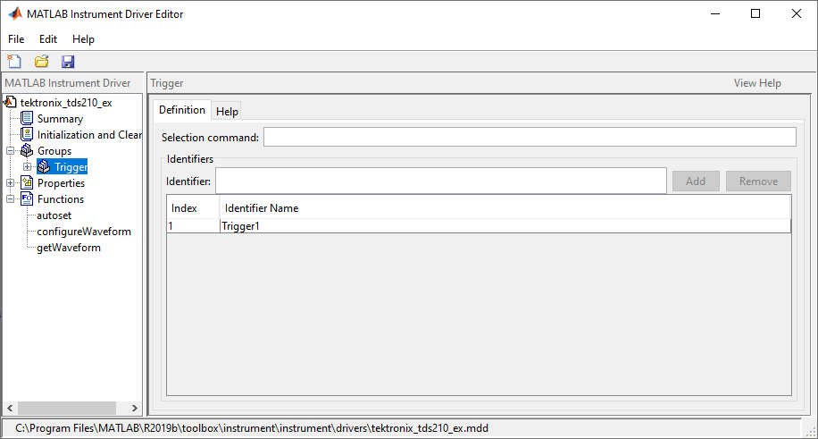
This example combines the trigger capabilities of the Tektronix® TDS 210 oscilloscope into a trigger group. The oscilloscope allows the trigger source and slope settings to be configured. In the MATLAB instrument driver editor,
Select the
Groupsnode in the tree.Enter the group name,
Trigger, in the Add Group text field and click Add.Expand the
Groupsnode to display all the defined groups.Select the
Triggernode in the tree.Select the Definition tab.
Since the oscilloscope has only one trigger, there is not a command that will select the current trigger. The Selection command text field will remain empty.
Select the Help tab to finish defining the group behavior.
In the Help text field, enter
Trigger is a trigger group. The trigger group object contains properties that configure and query the oscilloscope's triggering capabilities.Click the Save button.
Verifying the Group Behavior. This procedure verifies the group information defined. In this
example, the driver name is tektronix_tds210_ex.mdd.
Communication with the Tektronix TDS 210 oscilloscope at primary
address 2 is done via a Measurement Computing™ Corporation GPIB
board at board index 0. From the MATLAB command line,
Create the device object,
obj, using theicdevicefunction.g = gpib('mcc',0,2); obj = icdevice('tektronix_tds210_ex.mdd',g);
View the group you created. Note that the
HwNameproperty is the group object identification string.obj.Trigger
   HwIndex:    HwName:     Type:            Name:
   1           Trigger1    scope-trigger    Trigger1
View the help.
instrhelp(obj, 'Trigger')TRIGGER Trigger is a trigger group. The trigger group object contains properties that configure and query the oscilloscope's triggering capabilities.
Delete the objects.
delete([obj g])
Defining the Group Object Properties for a One-Element Group
This example defines the properties for the Trigger group
object created in the previous example. The Tektronix TDS 210
oscilloscope can trigger from CH1 or CH2 when the data has a rising
or falling slope.
First, the properties Source and Slope are
added to the trigger group object. In the MATLAB instrument driver
editor,
Expand the
Triggergroup node to display the group object's properties and functions.Select the
Propertiesnode to define theTriggergroup object properties.Enter the property name
Sourcein the Add property text field and click the Add buttonEnter the property name
Slopein the Add property text field and click the Add button.Expand the
Propertiesnode to display the group object's properties.
Next, define the behavior of the Source property:
Select the
Sourcenode in the tree.Select the Code tab to define the
setandgetcommands for theSourceproperty.Select
Instrument Commandsin the Property style field.Enter
TRIGger:MAIn:EDGE:SOUrce?in the Get command text field.Enter
TRIGger:MAIn:EDGE:SOUrcein the Set command text field.
Select the Property Values tab to define the allowed property values.
Select
Stringin the Data Type field.Select
Enumerationin the Constraint field.Enter
CH1in the Add property value text field and click the Add button. Then enterCH1in the Instrument Value table field.Similarly, add the enumeration:
CH2,CH2.
Select the Help tab to finish defining the property behavior.
Enter
CH1in the Default value text field.Select
neverin the Read only field.In the Help text field, enter
Specifies the source for the main edge
                                        trigger
.
Next, define the behavior of the Slope property:
Select the
Slopenode in the tree.Select the Code tab to define the set and get commands for the
Slopeproperty.Select
Instrument Commandsin the Property style field.Enter
TRIGger:MAIn:EDGE:SLOpe?in the Get command text field.Enter
TRIGger:MAIn:EDGE:SLOpein the Set command text field.
Select the Property Values tab to define the allowed property values.
Select
Stringin the Data Type field.Select
Enumerationin the Constraint field.Enter
fallingin the Add property value text field and click the Add button. Then enterFALLin the Instrument Value table field.Similarly add the enumeration:
rising,RISe.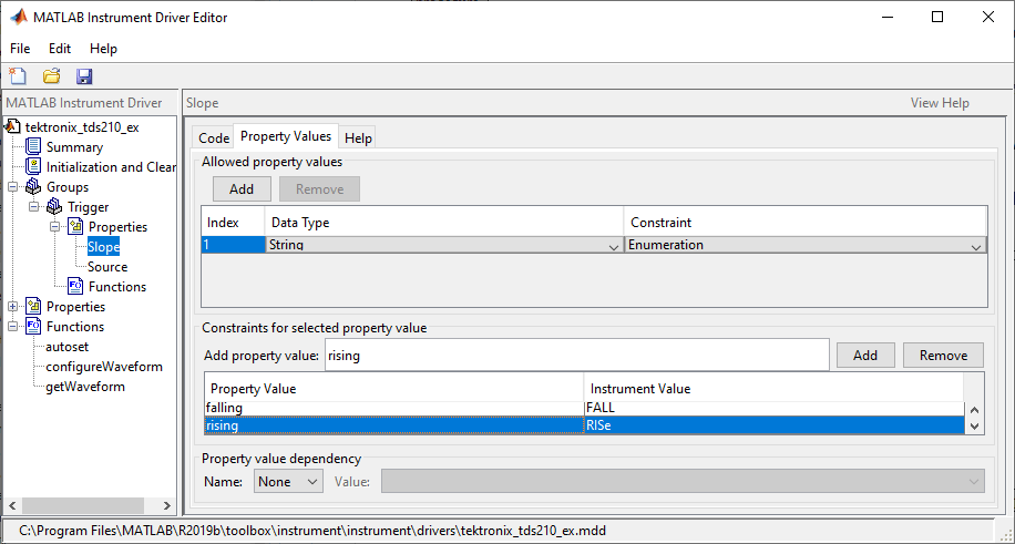
Select the Help tab to finish defining the property behavior.
Enter
fallingin the Default value text field.Select
neverin the Read only field.In the Help text field, enter
Specifies a rising or falling slope for the main
                                        edge trigger
.
Click the Save button.
Verifying Properties of the Group Object in MATLAB. This procedure verifies the properties of the Trigger group
object. In this example, the driver name is tektronix_tds210_ex.mdd.
Communication with the Tektronix TDS 210 oscilloscope at primary
address 2 is done via a Measurement Computing Corporation GPIB
board at board index 0. From the MATLAB command line,
Create the device object,
obj, using theicdevicefunction.g = gpib('mcc',0,2); obj = icdevice('tektronix_tds210_ex.mdd',g);
Extract the trigger group objects,
t, from the device object.t = obj.Trigger
   HwIndex:    HwName:     Type:            Name:
   1           Trigger1    scope-trigger    Trigger1
Access specific properties to list its current value.
t.Source
ans =

    'CH1'
t.Slope
ans =

    'falling'
Calling
seton a specific property lists the values to which you can set the property.set(t,'Source')[ {CH1} | CH2 ]set(t,'Slope')[ {falling} | rising ]Try setting the property to valid and invalid values.
t.Source = 'CH2';
t.Slope = 'rising';
t.Source
ans =

    'CH2'
t.Slope
ans =

    'rising'
t.Source = 'CH3'There is no enumerated value named 'CH3'.
t.Slope = 'steady'There is no enumerated value named 'steady'.
View the help you wrote.
instrhelp(t,'Source')SOURCE [ {CH1} | CH2 ] Specifies the source for the main edge trigger.instrhelp(t,'Slope')SLOPE [ {falling} | rising ] Specifies a rising or falling slope for the main edge trigger.List the group object characteristics that you defined in the Property Values and Help tabs.
propinfo(t,'Source')ans = struct with fields: Type: 'string' Constraint: 'enum' ConstraintValue: {2×1 cell} DefaultValue: 'CH1' ReadOnly: 'never' InterfaceSpecific: 1propinfo(t,'Slope')ans = struct with fields: Type: 'string' Constraint: 'enum' ConstraintValue: {2×1 cell} DefaultValue: 'falling' ReadOnly: 'never' InterfaceSpecific: 1Connect to your instrument to verify the
setandgetcode.connect(obj)
Note
When you issue the
getfunction on theSourceproperty for the trigger object, thetextronix_tds210_ex.mdddriver actually sends theTRIGger:MAIn:EDGE:SOUrce?command to the instrument.t.Source
ans =

    'CH1'
Note
When you issue the
setfunction on theSlopeproperty for the trigger object, thetextronix_tds210_ex.mdddriver actually sends theTRIGger:MAIn:EDGE:SLOpe RISecommand to the instrument.t.Slope = 'rising';Disconnect from your instrument and delete the objects.
disconnect(obj)
delete([obj g])
Creating a Four-Element Group
This example combines the measurement capabilities of the Tektronix TDS 210 oscilloscope into a measurement group. The oscilloscope allows four measurements to be taken at a time. In the MATLAB instrument driver editor,
Select the
Groupsnode in the tree.Enter the group name,
Measurement, in the Add group text field and click Add.Expand the
Groupsnode to display all the defined groups.Select the
Measurementnode in the tree.Select the Definition tab.
The oscilloscope does not define an instrument command that will define the measurement that is currently being calculated. The Selection command text field will remain empty.
In the Identifier Name listing, change
Measurement1toMeas1to define the identification string for the first measurement group object in the group.Enter the identifiers
Meas2,Meas3, andMeas4for the remaining measurement group objects by typing each in the Identifier text field and clicking Add after each.
Select the Help tab to finish defining the group behavior.
In the Help text field, enter
Measurement is an array of measurement group objects.
A measurement group object contains properties related to each supported
measurement on the oscilloscope
.
Click the Save button.
Verifying the Group Behavior. This procedure verifies the group information defined. In this
example, the driver name is tektronix_tds210_ex.mdd.
Communication with the Tektronix TDS 210 oscilloscope at primary
address 2 is done via a Measurement Computing Corporation GPIB
board at board index 0. From the MATLAB command line,
Create the device object,
obj, using theicdevicefunction.g = gpib('mcc',0,2); obj = icdevice('tektronix_tds210_ex.mdd',g);
View the group you created. Note that the
HwNameproperty is the group objectget(obj).obj.Measurement
   HwIndex:    HwName:    Type:                Name:
   1           Meas1      scope-measurement    Measurement1
   2           Meas2      scope-measurement    Measurement2
   3           Meas3      scope-measurement    Measurement3
   4           Meas4      scope-measurement    Measurement4
View the help.
instrhelp(obj,'Measurement')MEASUREMENT Measurement is an array of measurement group objects. A measurement group object contains properties related to each supported measurement on the oscilloscope.
Delete the objects.
delete([obj g])
Defining the Group Object Properties for a Four-Element Group
This example defines the properties for the Measurement group
object created in the previous example. The Tektronix TDS 210
oscilloscope can calculate the frequency, mean, period, peak to peak
value, root mean square, rise time, fall time, positive pulse width,
or negative pulse width of the waveform of Channel 1
or Channel 2.
First, the properties MeasurementType, Source, Value,
and Units will be added to the Measurement group
object.
Expand the
Measurementgroup node to display the group object's properties and methods.Select the
Propertiesnode to define theMeasurementgroup object properties.Enter the property name
MeasurementTypein the Add property text field and click the Add button.Enter the property name
Sourcein the Add property text field and click the Add button.Enter the property name
Valuein the Add property text field and click the Add button.Enter the property name
Unitsin the Add property text field and click the Add button.Expand the
Propertiesnode to display the group object's properties.
Next, define the behavior of the MeasurementType property:
Select the
MeasurementTypenode in the tree.Select the Code tab to define the
setandgetcommands for theMeasurementTypeproperty.Select
Instrument Commandsin the Property style field.Enter
Measurement:<ID>:Type?in the Get command text field.Enter
Measurement:<ID>:Typein the Set command text field.
Select the Property Values tab to define the allowed property values.
Select
Stringin the Data Type field.Select
Enumerationin the Constraint field.Enter
frequencyin the Add property value text field and click the Add button. Then enterFREQuencyin the Instrument Value table field.Add the enumeration:
mean,MEAN.Add the enumeration:
period,PERIod.Add the enumeration:
pk2pk,PK2pk.Add the enumeration:
rms,CRMs.Add the enumeration:
riseTime,RISe.Add the enumeration:
fallTime,FALL.Add the enumeration:
posWidth,PWIdth.Add the enumeration:
negWidth,NWIdth.Add the enumeration:
none,NONE.
Select the Help tab to finish defining the property behavior.
Enter
nonein the Default value text field.Select
neverin the Read only field.In the Help text field, enter
Specifies the measurement type.
Next, define the behavior of the Source property.
Select the
Sourcenode in the tree.Select the Code tab to define the
setandgetcommands for theSourceproperty.Select
Instrument Commandsin the Property style field.Enter
Measurement:<ID>:Source?in the Get command field.Enter
Measurement:<ID>:Sourcein the Set command field.
Select the Property Values tab to define the allowed property values.
Select
Stringin the Data Type field.Select
Enumerationin the Constraint field.Enter
CH1in the Add property value text field and click the Add button. Then enterCH1in the Instrument Value table field.Similarly add the enumeration:
CH2,CH2.
Select the Help tab to finish defining the property behavior.
Enter
CH1in the Default value text field.Select
neverin the Read only field.In the Help text field, enter
Specifies the source of the
                                    measurement
.
Next, define the behavior of the Units property.
Select the
Unitsnode in the tree.Select the Code tab to define the
setandgetcommands for theUnitsproperty.Select
Instrument Commandsin the Property style field.Enter
Measurement:<ID>:Units?in the Get command text field.Since the
Unitsproperty is read-only, leave the Set command text field empty.
Select the Property Values tab to define the allowed property values.
Select
Stringin the Data Type field.Select
Nonein the Constraint field.
Select the Help tab to finish defining the property behavior.
Enter
voltsin the Default value text field.Select
alwaysin the Read only field.In the Help text field, enter
Returns the measurement units.
Finally, define the behavior of the Value property.
Select the
Valuenode in the tree.Select the Code tab to define the
setandgetcommands for theValueproperty.Select
Instrument Commandsin the Property style field.Enter
Measurement:<ID>:Value?in the Get command text field.Since the
Valueproperty is read-only, leave the Set command text field empty.
Select the Property Values tab to define the allowed property values.
Select
Doublein the Data Type field.Select
Nonein the Constraint field.
Select the Help tab to finish defining property behavior.
Enter
0in Default value field.Select
alwaysin the Read only field.In the Help text field, enter
Returns the measurement value.
Click the Save button.
Verifying the Properties of the Group Object in the MATLAB software. This procedure verifies the properties of the measurement group
object. In this example, the driver name is tektronix_tds210_ex.mdd.
Communication with the Tektronix TDS 210 oscilloscope at primary
address 2 is done via a Measurement Computing Corporation GPIB
board at board index 0. From the MATLAB command line,
Create the device object,
obj, using theicdevicefunction.g = gpib('mcc',0,2); obj = icdevice('tektronix_tds210_ex.mdd',g);
Extract the measurement group objects,
m, from the device object.m = obj.Measurement
   HwIndex:    HwName:    Type:                Name:
   1           Meas1      scope-measurement    Measurement1
   2           Meas2      scope-measurement    Measurement2
   3           Meas3      scope-measurement    Measurement3
   4           Meas4      scope-measurement    Measurement4
View the current values for the properties of the first group object. Calling
geton the object lists all its properties.m(1)
   HwIndex:    HwName:    Type:                Name:
   1           Meas1      scope-measurement    Measurement1
Calling
geton a specific property lists its current value.m(1).MeasurementType
ans =

    'none'
m(1).Source
ans =

    'CH1'
m(1).Units
ans =

    'volts'
m(1).Value
ans =

     0
View the acceptable values for the properties of the group object. Calling
seton the object lists all its settable properties.set(m(1))
Name: SCOPE-MEASUREMENT specific properties: MeasurementType: [ frequency | mean | period | pk2pk | rms | riseTime | fallTime | posWidth | negWidth | {none} ] Source: [ {CH1} | CH2 ]set(m(1),'MeasurementType')[ frequency | mean | period | pk2pk | rms | riseTime | fallTime | posWidth | negWidth | {none} ]set(m(1),'Source')
[ {CH1} | CH2 ]Try setting the property to valid and invalid values.
m(1).Source = 'CH2'HwIndex: HwName: Type: Name: 1 Meas1 scope-measurement Measurement1 2 Meas2 scope-measurement Measurement2 3 Meas3 scope-measurement Measurement3 4 Meas4 scope-measurement Measurement4
m(1).Source
ans =

    'CH2'
m(1).Source = 'CH5'There is no enumerated value named 'CH5'.
View the help you wrote.
instrhelp(m(1),'Value')VALUE (double) (read only) Returns the measurement value.
List the group object characteristics that you defined in the Property Values and Help tabs.
propinfo(m(1),'Units')ans = struct with fields: Type: 'string' Constraint: 'none' ConstraintValue: '' DefaultValue: 'volts' ReadOnly: 'always' InterfaceSpecific: 1Connect to your instrument to verify the
setandgetcode.connect(obj)
Note
When you issue the
getfunction on theMeasurementTypeproperty for the first measurement object in the group, thetextronix_tds210_ex.mdddriver actually sends theMeasurement:Meas1:Type?command to the instrument.m(1).MeasurementType
ans =

    'freequency'
Note
When you issue the
setfunction on theSourceproperty for the second measurement object in the group, thetextronix_tds210_ex.mdddriver actually sends theMeasurement:Meas2:Source CH2command to the instrument.m(2).Source = 'CH2';Disconnect from your instrument and delete the objects.
disconnect(obj)
delete([obj g])