How the Solver Calculates Simscape Fluids Block Equations
Simscape™ Fluids™ blocks use one-dimensional lumped parameter models. These models use a combination of differential equations to model dynamics and algebraic equations to model instantaneous relationships and constraints. The solver uses these block equations, along with block equations from any other Simscape domains in the model, to create a system of equations that solves at each time step until convergence. For more information about how Simscape solves the equations in a model, see How Simscape Simulation Works.
The Upwind Numerical Scheme
The solver performs calculations at each port and internal node of every block in the fluid network. To solve a network, the solver calculates the Across variable that defines the energy in the fluid at each port or internal node with the upwind numerical scheme. In the upwind scheme, the energy carried by the fluid at the port or internal node, which is the specific internal energy in the two-phase fluid domain and the temperature in the other domains, is equal to the energy of the fluid upstream of the node.
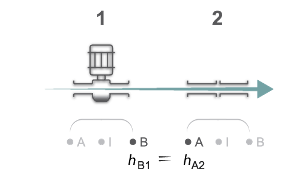
This diagram shows two blocks in a network. Each block has a port A and B and an internal node, I. When the fluid is flowing, the solver calculates the fluid behavior according to the flow direction. In this example, the specific total enthalpy in block 2 at port A, hA2, is equal to the specific total enthalpy, hB1, at port B of block 1, by definition of across variables. With the upwind scheme, these values are also equal to the specific total enthalpy at the internal node of block 1, hI1.

When the fluid flows in the reverse direction, the solver calculates the specific total enthalpy at port A of block 2 from the specific total enthalpy of the internal node I, hI2, of the same component. In this case, hB1=hA2=hI2.

When you connect three or more blocks, the unwinding impact on the fluid energy Across variable depends on the block arrangement:
Flow leaves one block, splits at a node, and enters two or more blocks — The individual block is upstream. The downstream blocks both receive the fluid energy that leaves this block.
Flow leaves two or more blocks, merges at a node, and enters one block — The two or more blocks are upstream. The individual downstream block receives the weighted average, by mass flow rate, of the fluid energy leaving the upstream blocks.
Because of the upwind scheme, you may observe differences in measured variable values depending on the flow direction and interrogated node. When there is no fluid flow, the fluid properties at all nodes diffuse via numerical conduction.
How the Solver Applies Smoothing
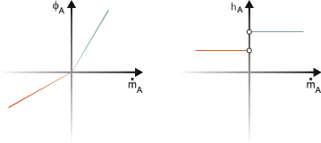
At time steps where the flow changes direction, the mass flow rate crosses 0. This crossing causes the specific total enthalpy to jump when the flow rate is exactly zero. This discontinuity impacts the solver performance and may cause unexpected results.

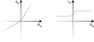
To avoid discontinuities, the solver applies smoothing to the calculations and calculates the fluid values in terms of energy flows. In the above example, the smoothed energy flux at port A is equal to the sum of the energy flow rate and the specific total enthalpy conduction between port A and internal node I. Under nominal block conditions, conduction contributes to numerical smoothing but contributes negligibly to the energy flow rate. When the flow rate close to zero, the block smooths the specific total enthalpy.

The total energy flow rate at each block node depends on the fluid flow direction
where:
ΦA is the energy flow rate through port A, including the numerical conduction between port A and the internal node I.
G is the thermal conductance coefficient, which for thermal liquid and moist air domains is
where:
k is the thermal conductivity.
S is the port cross-sectional area.
cv is the fluid specific heat.
L is the characteristic length between the port and internal node.
Quasi-steady components also account for energy flow rate smoothing. Although quasi-steady blocks do not have an internal volume, the solver calculates the difference between internal enthalpy and enthalpy at the block ports.
For the two-phase and gas domains, G is a general tuning parameter defined by domain threshold parameters. Increasing the value of the Mach number threshold for flow reversal parameter in the Gas Properties (G) block increases the amount of energy flow smoothing. Similarly, increasing the value of the Dynamic pressure threshold for flow reversal parameter in the Two-Phase Fluid Properties (2P) or Two-Phase Fluid Predefined Properties (2P) block increases the smoothing region.
For more information on flow reversals, see Change Flow Direction.
Impact of Upwind Smoothing on Energy Flow Rate
When the flow rate through a port is zero, the numerical conduction for smoothing can have an unexpected impact on the energy flow rate. Even if the mass flow rate is zero, the energy flow rate can be nonzero if there is an energy difference in the fluid on either side of the port. Because the numerical conduction contribution to the energy flow rate is typically very small compared to the contribution from convection, it is negligible when the flow rate is nonzero.
If the model experiences zero or near-zero flow rate for long periods of time, the numerical conduction contribution to the energy flow rate may be noticeable. To avoid this situation, set the port cross-sectional area parameter to a value close to the pipe size in your application area.
If adjusting the port cross-sectional area parameter does not reduce the contribution to energy flow rate, you can adjust other parameters. In the gas domain, reduce the Mach number threshold for flow reversal parameter. In the two-phase fluid domain, reduce the Dynamic pressure threshold for flow reversal parameter. However, setting these parameter values too small can make the simulation less robust during rapid flow reversals because it reduces the discontinuity smoothing described above.