生成されたコードでの配列サイズのシンボリック次元の実装
シンボリック次元により、モデル開発時に次元に固定数値の代わりにシンボルを使用できます。モデル内で信号の次元を指定する必要がある場合はいつでも、実際の数値の代わりにシンボリック次元を使用できます。そのため、次元を柔軟に変更できます。詳細については、Use Symbolic Signal Dimensions を参照してください。
この例では、ベクトルと行列を含む 4 つのモデル化パターンをもつモデル DimensionVariants にシンボリック次元を実装する方法と、CompilerFlag ストレージ クラスおよび ImportedDefine ストレージ クラスを使用してコードを生成する方法を示します。
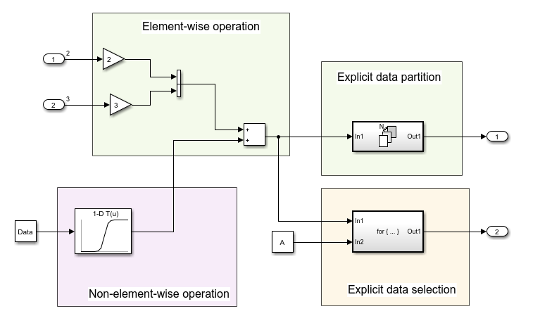
ブロック名を表示するには、[デバッグ] タブで [情報オーバーレイ] を選択し、[自動ブロック名の非表示] をオフにします。
Embedded Coder アプリを開きます。[C コード] タブで、[コード インターフェイス]、[個々の要素コードのマッピング] を選択します。コード マッピング エディターの [パラメーター] タブで、[リフレッシュ] をクリックします。7 つの Simulink.Parameter オブジェクトが表示され、そのうちの 4 つがシンボリック次元 A、B、C、および D を指定しています。これらのパラメーターのストレージ クラスは CompilerFlag です。
ブロックとデータ オブジェクトのシンボリック次元の指定
Simulink ツールストリップの [モデル化] タブで、[設計] ギャラリーから [プロパティ インスペクター] を選択します。
Inport ブロック
In1をクリックします。プロパティ インスペクターで、[端子の次元] プロパティがSimulink.ParameterオブジェクトAに設定されています。Inport ブロック
In2をクリックします。[端子の次元] プロパティがSimulink.ParameterオブジェクトBに設定されています。Constant ブロックをクリックします。[定数値] プロパティが
Simulink.ParameterオブジェクトDataに設定されています。コード マッピング エディターの [パラメーター] タブで、
Simulink.ParameterオブジェクトDataをクリックします。[次元] フィールドには文字ベクトル'[1,C]'が含まれています。これは、Cの値が5であるため、'[1,5]'と等価です。[値] プロパティには、その次元と一致する 1 行 5 列の配列が含まれています。データ オブジェクトの次元は、[次元] フィールド内のSimulink.Parameterオブジェクトの値と一致している必要があります。Dataの [ストレージ クラス] はImportedExternです。1-D Lookup Table1ブロック パラメーター ダイアログ ボックスを開きます。[テーブル データ] パラメーターはSimulink.ParameterPTに設定されています。[ブレークポイント 1] フィールドに、Simulink.ParameterPBが含まれています。コード マッピング エディターで、
PBおよびPTをクリックし、そのプロパティを表示します。これらのパラメーターは、[次元] プロパティが'[1,D]'に設定されており、1 行 15 列の配列であり、Dの値15と一致しています。
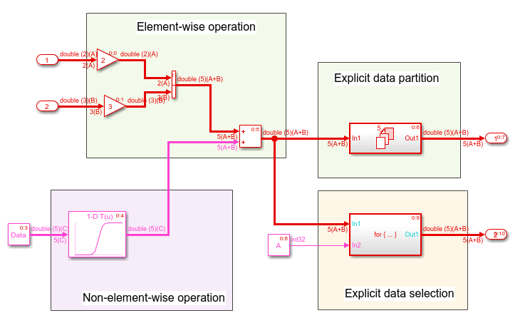
モデルのシミュレーションを実行します。Simulink は、ブロック線図で次元をシンボリックに伝播します。
コードの生成
モデル シミュレーションによって次元の仕様を検証した後に、DimensionVariants のコードを生成します。
モデルをビルドします。
model = "DimensionVariants";
slbuild(model);
### Searching for referenced models in model 'DimensionVariants'. ### Total of 1 models to build. ### Starting build procedure for: DimensionVariants ### Successful completion of build procedure for: DimensionVariants Build Summary Top model targets: Model Build Reason Status Build Duration ==================================================================================================================== DimensionVariants Information cache folder or artifacts were missing. Code generated and compiled. 0h 0m 27.345s 1 of 1 models built (0 models already up to date) Build duration: 0h 0m 29.964s
生成されたコードを表示します。DimensionVariants.h ファイルでは、シンボリック次元はデータ宣言に含まれています。
hfile = fullfile('DimensionVariants_ert_rtw',...
    'DimensionVariants.h');
coder.example.extractLines(hfile,'/* External inputs', '/* Real-time', 1, 0);
/* External inputs (root inport signals with default storage) */
typedef struct {
  real_T In1[A];                       /* '<Root>/In1' */
  real_T In2[B];                       /* '<Root>/In2' */
} ExtU;

/* External outputs (root outports fed by signals with default storage) */
typedef struct {
  real_T Out1[(A + B)];                /* '<Root>/Out1' */
  real_T Out2[(A + B)];                /* '<Root>/Out2' */
} ExtY;
シンボリック次元は、ヘッダー ファイルではマクロとして定義されています。
hfile = fullfile('DimensionVariants_ert_rtw',...
    'DimensionVariants.h');
coder.example.extractLines(hfile,'#ifndef A', '* Constraints for division operations', 1, 0);
#ifndef A
#error The value of parameter "A" is not defined
#endif

#ifndef B
#error The value of parameter "B" is not defined
#endif

#ifndef C
#error The value of parameter "C" is not defined
#endif

#ifndef D
#error The value of parameter "D" is not defined
#endif

/*
DimensionVariants.h ファイルには、シミュレーション中にシンボル間に確立される制約を定義するデータ定義とプリプロセッサの条件が含まれています。これらの制約の 1 つとして、シンボリック次元の値は 1 より大きくなければなりません。
hfile = fullfile('DimensionVariants_ert_rtw',...
    'DimensionVariants.h');
coder.example.extractLines(hfile,'#if A <= 1', '/* Macros for accessing', 1, 0);
#if A <= 1
# error "The preprocessor definition 'A' must be greater than '1'"
#endif

#if B <= 1
# error "The preprocessor definition 'B' must be greater than '1'"
#endif

/* Constraint 'D > 1' registered by:
 * '<Root>/1-D Lookup Table1'
 */
#if D <= 1
# error "The preprocessor definition 'D' must be greater than '1'"
#endif

/* Constraint 'C > 3' registered by:
 * '<S2>/Assignment'
 */
#if C <= 3
# error "The preprocessor definition 'C' must be greater than '3'"
#endif

#if A >= 11
# error "The preprocessor definition 'A' must be less than '11'"
#endif

#if B >= 11
# error "The preprocessor definition 'B' must be less than '11'"
#endif

/* Constraint 'D < 21' registered by:
 * '<Root>/1-D Lookup Table1'
 */
#if D >= 21
# error "The preprocessor definition 'D' must be less than '21'"
#endif

/* Constraint 'C < 11' registered by:
 * '<S2>/Assignment'
 */
#if C >= 11
# error "The preprocessor definition 'C' must be less than '11'"
#endif
DimensionVariants.h ファイルには、ImportedDefine カスタム ストレージ クラスをもつ Simulink.Parameter オブジェクトに対してユーザーが提供するヘッダー ファイルも含まれます。
DimensionVariants.c ファイルでは、シンボリック次元はループ境界計算、配列サイズとインデックス オフセットの計算、パラメーター化されたユーティリティ関数 (Lookup Table ブロックなど) の計算で使用されます。
cfile = fullfile('DimensionVariants_ert_rtw',...
    'DimensionVariants.c');
coder.example.extractLines(cfile,'/* Model step', '/* Model initialize', 1, 0);
/* Model step function */
void DimensionVariants_step(void)
{
  real_T rtb_VectorConcatenate[A + B];
  real_T rtb_VectorConcatenate_0;
  int32_T ForEach_itr;
  int32_T i;
  int32_T s2_iter;

  /* Gain: '<Root>/Gain' incorporates:
   *  Inport: '<Root>/In1'
   */
  for (ForEach_itr = 0; ForEach_itr < A; ForEach_itr++) {
    rtb_VectorConcatenate[ForEach_itr] = 2.0 * rtU.In1[ForEach_itr];
  }

  /* End of Gain: '<Root>/Gain' */

  /* Gain: '<Root>/Gain1' incorporates:
   *  Inport: '<Root>/In2'
   */
  for (ForEach_itr = 0; ForEach_itr < B; ForEach_itr++) {
    rtb_VectorConcatenate[A + ForEach_itr] = 3.0 * rtU.In2[ForEach_itr];
  }

  /* End of Gain: '<Root>/Gain1' */

  /* Outputs for Iterator SubSystem: '<Root>/For Each Subsystem' incorporates:
   *  ForEach: '<S1>/For Each'
   */
  for (ForEach_itr = 0; ForEach_itr < (A + B); ForEach_itr++) {
    /* Sum: '<Root>/Add' incorporates:
     *  Constant: '<Root>/Constant'
     *  Lookup_n-D: '<Root>/1-D Lookup Table1'
     */
    rtb_VectorConcatenate_0 = look1_binlx(Data[ForEach_itr], PB, PT, (uint32_T)
      ((int32_T)(D - (int32_T)1))) + rtb_VectorConcatenate[ForEach_itr];
    rtb_VectorConcatenate[ForEach_itr] = rtb_VectorConcatenate_0;

    /* ForEachSliceAssignment generated from: '<S1>/Out1' incorporates:
     *  ForEachSliceSelector generated from: '<S1>/In1'
     *  MATLAB Function: '<S1>/MATLAB Function'
     */
    /* MATLAB Function 'For Each Subsystem/MATLAB Function': '<S3>:1' */
    /* '<S3>:1:4' y = 2*u; */
    rtY.Out1[ForEach_itr] = 2.0 * rtb_VectorConcatenate_0;
  }

  /* End of Outputs for SubSystem: '<Root>/For Each Subsystem' */

  /* Outputs for Iterator SubSystem: '<Root>/For Iterator Subsystem' incorporates:
   *  ForIterator: '<S2>/For Iterator'
   */
  /* Constant: '<Root>/Constant1' */
  ForEach_itr = ((int32_T)A);
  if (((int32_T)A) < (int8_T)0) {
    ForEach_itr = 0;
  }

  /* End of Constant: '<Root>/Constant1' */
  for (s2_iter = 0; s2_iter < ForEach_itr; s2_iter++) {
    /* Assignment: '<S2>/Assignment' incorporates:
     *  Constant: '<S2>/Constant'
     *  Outport: '<Root>/Out2'
     *  Product: '<S2>/Product'
     *  Selector: '<S2>/Selector'
     */
    if (s2_iter == (int8_T)0) {
      for (i = 0; i < (A + B); i++) {
        rtY.Out2[i] = rtb_VectorConcatenate[i];
      }
    }

    rtY.Out2[s2_iter] = rtb_VectorConcatenate[s2_iter] * 2.0;

    /* End of Assignment: '<S2>/Assignment' */
  }

  /* End of Outputs for SubSystem: '<Root>/For Iterator Subsystem' */
}
シンボリック次元の値はコンパイル時に固定する必要があります。シミュレーション中に動作を定義するため、シンボリック次元を別の変数に解決して実行時に変更することはできません。
バリアント選択肢に基づいたパラメーター値の設定
シンボルを使用してモデル内のパラメーターの次元を指定する場合は、パラメーター値が次元値と一致していることを確認する必要があります。次元値に対してさまざまな選択肢をシミュレーションするには、パラメーター値を手動で修正します。
たとえば、DimensionVariants モデルでは、Simulink.Parameter オブジェクト Data はベクトル値 [1 2 3 4 5] を格納し、初期値 5 のシンボリック次元 C を使用します。C の値を変更する場合は、モデルをシミュレーションするために、ベクトルの長さが C の新しい値と一致することを確認してください。
C の値を変更する際のメンテナンスの手間を軽減するために、Data の値を、C を含む式に設定できます。
MATLAB コード構文では、Data の値は [1:C] です。パラメーター オブジェクト間でこの関係を維持するには、slexpr 関数を使用して Data の値を設定します。
Data.Value = slexpr('1:C')
複雑なアプリケーションの場合は、シンボリック次元に基づいてパラメーター値を返す独自の MATLAB 関数を作成できます。パラメーター Data の値を、関数を呼び出す式に設定します。式を使用して Simulink.Parameter オブジェクトの値を設定する方法の一般情報については、数式を使用した変数値の設定を参照してください。
ヒント:
シンボリック次元を含む Simulink.Parameter オブジェクトの初期化コードを指定する必要があります。生成されたコードがこれらのパラメーターを初期化しないようにするには、次のいずれかを行う必要があります。
ImportedExternやImportedExternPointer組み込みストレージ クラスなど、[データ スコープ] プロパティがImportedに設定されたストレージ クラスを使用するようにパラメーターを構成する。[データの初期化] プロパティが
Noneに設定されたストレージ クラスを使用するようにパラメーターを構成する。