Getting Started with ADC Using MCAL
This topic explains how analog-to-digital conversion (ADC) works when using the MCAL ADC block in Simulink. It explains the supported ADC concepts, execution models, and usage patterns so that you can design a valid and predictable ADC workflow before applying it in a specific example or target project.
The MCAL ADC block maps directly to AUTOSAR ADC services. Configuration choices such as triggering, buffering, and result access determine how conversions are executed and how data becomes available to the application. Understanding these relationships helps you select an ADC pattern that meets your timing, performance, and data access requirements.
This topic covers multiple ADC workflows that differ in how conversions are started and how results are consumed. You can use these workflows to align ADC behavior with your timing, synchronization, and data access requirements.
This topic assumes that the AUTOSAR MCAL configuration for the ADC, Port, and related timer modules has already been created using r DaVinci Configurator. The exported configuration (CDF/ARXML) defines ADC groups, trigger sources, and pin mappings that the MCAL ADC blocks rely on at run time.
See Configuring MCAL Modules Using DaVinci for details on creating and exporting MCAL configuration data used by the ADC workflow.
Key Workflows Demonstrated
This topic describes two primary ADC usage patterns:
Software-triggered acquisition — The model explicitly starts and stops conversions. This approach provides deterministic control over when sampling occurs and is suitable for algorithm-driven sampling.
Hardware-triggered acquisition — A hardware event starts conversions. This approach aligns sampling with external timing sources and is suitable for time-critical or synchronized measurements.
Choose the workflow that best matches how your application coordinates sampling with control logic or hardware events.
What the MCAL ADC Block Represents
The MCAL ADC block represents AUTOSAR ADC services and is generated from an ADC template. The block behavior follows the AUTOSAR ADC specification and its state machine. Configuration choices in the block determine how the AUTOSAR services are exercised at run time.
You can extend the template workflow to fit your application needs, but you cannot change the underlying AUTOSAR-defined execution rules. Understanding these rules is essential to avoid invalid configurations, missed samples, or stalled execution.
Supported ADC Capabilities
In the current release, the MCAL ADC block supports the following capabilities:
Conversion modes: one-shot and continuous.
Trigger sources: software trigger and hardware trigger.
Buffer mode: linear buffer only.
Samples per channel: one sample per channel.
Access modes: single access and streaming access.
These constraints define which ADC workflows are valid and how results can be read.
Key ADC Concepts
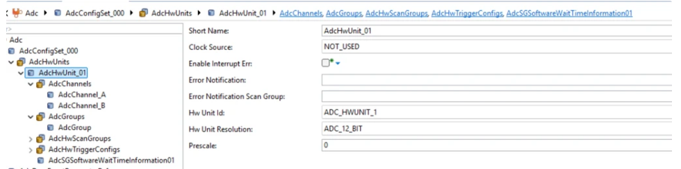
ADC Channels and Groups
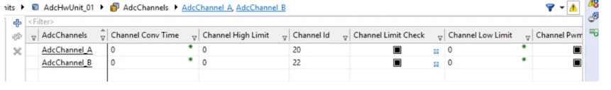
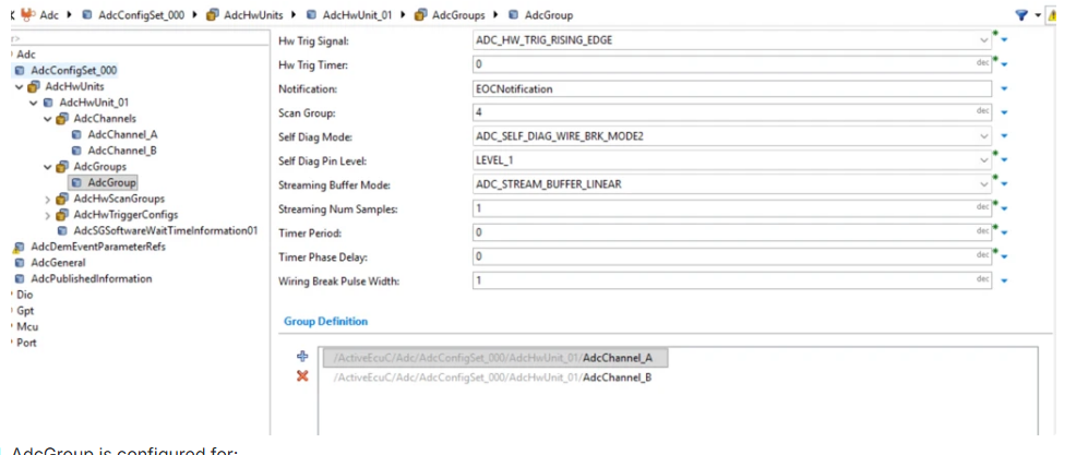
ADC channels represent individual analog inputs. Channels are organized into ADC groups, which are the unit of conversion, triggering, buffering, and notification. All control and result access operate at the group level. Individual channels cannot be triggered or read independently.
All triggering, buffering, and notification behavior is defined at the group level. Individual channels cannot be triggered or read independently.
Trigger Sources
ADC conversion can be initiated by:
Software trigger, initiated explicitly from the model.
Hardware trigger, initiated by a configured hardware event.
The trigger source determines how conversion starts and how the group transitions between AUTOSAR ADC states.
Synchronized Sampling with GPT
For hardware-triggered ADC groups, the conversion can be synchronized to timer events generated by GPT. In this workflow, the timer generates a periodic trigger event, and the ADC group is configured to start conversion on each event. This enables deterministic and phase-aligned sampling, for example, sampling synchronized to PWM edges or control-loop timing. This approach is recommended for closed-loop control and time-critical signal acquisition where software-triggered sampling jitter is not acceptable.
Conversion Modes
In one-shot mode, the ADC group performs a single conversion round and then stops. In continuous mode, the ADC group continues converting until explicitly stopped. Continuous mode is supported only with software triggering.
Buffering and Access Mode
The ADC result buffer stores group results using a linear buffer. With linear buffering, results are written sequentially and only one sample per channel is supported. Results must be read before the group returns to the idle state.
Access mode determines when results become available and how reading results affects group state.
ADC–Port Interaction
ADC channels sample analog voltages from MCU pins that are configured for ADC functionality in the Port module. Ensure that the corresponding pins are configured with the correct alternate function (analog input mode) and appropriate electrical characteristics (for example, input direction and disabled digital pull-ups). If a pin is not configured for ADC in the Port configuration, the ADC group conversion can start successfully, but the sampled value at the hardware level is undefined or invalid. Always verify that the ADC channel configuration in the MCAL configuration data maps to Port pins configured for ADC operation.
AUTOSAR ADC State Model
The MCAL ADC block follows the AUTOSAR ADC state machine. At a high level, an ADC group transitions between idle, busy, and completed states. Reading results can trigger a state transition depending on trigger source and conversion mode. In many workflows, reading results returns the group to the idle state, which means previously produced results are no longer available unless a new conversion is started.
Choosing a Valid ADC Workflow
Select an ADC workflow based on how your application acquires and consumes analog data. Key considerations include how frequently new samples are required, whether sampling must be synchronized with hardware events, whether interrupt-driven processing is needed, and when and where conversion results are accessed.
A valid ADC workflow must comply with the rules of AUTOSAR ADC services:
Start a conversion only when the associated ADC group is idle.
Read conversion results only after the conversion has completed.
Explicitly stop continuous conversions when no further samples are required.
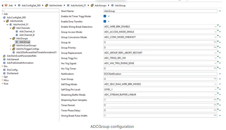
Selecting the Appropriate ADC Group Configuration
When configuring ADC groups in the MCAL configuration data, ensure that:
The configured ADC channels correspond to valid ADC-capable pins on the target hardware.
The trigger source (software or hardware) matches the intended execution model in the Simulink model.
The conversion mode (one-shot or continuous) aligns with how conversion results are consumed (polled reads or interrupt-driven processing).
The buffer configuration and number of channels match the block parameter settings in the model.
Notification (interrupt) is enabled for workflows that rely on hardware-triggered or interrupt-driven result processing.
A mismatch between the MCAL configuration and block parameters can lead to missing samples, stale data, or ADC group state errors at runtime.
See Also
Configuring MCAL Modules Using DaVinci | Using MCAL ADC and Hardware Interrupt Blocks with Renesas RH850 Microcontrollers