Service Mappings Editor
R2026bDescription
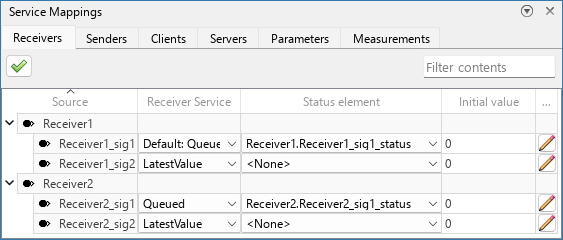
The Service Mappings editor is a graphical interface where you map model elements to service interface definitions.
This page describes the Embedded Linux® version of the Service Mappings Editor. To learn about the AUTOSAR Adaptive version, see Service Mappings Editor (AUTOSAR Blockset).
When you generate code from a model, the code generator uses the service interface definitions to generate the parts of the code that interface with target platform services. To learn more about mapping model elements to service interfaces, see Configure Model Elements with Service Interface Definitions for Code Generation.
Each of the tabs in the Service Mappings editor represents a category of services. Navigate to the tab of the category whose elements you want to map to services. Each tab contains a table, where each entry corresponds to one model element that is mapped to a service. Each column of the table corresponds to one property of the category service. To update the property value for a model element, specify the value in the corresponding table cell.
Open the Service Mappings Editor
To open the Service Mappings editor, do one of these:
Press Ctrl+Shift+C.
In the Simulink® Toolstrip, on the Apps tab, select Software Component Designer. Then, in the Software Component tab, click Service Mappings.
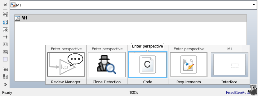
Click the bottom right corner of the model canvas to open the perspective views. Then, select Code perspective.
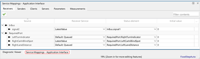
The Service Mappings editor opens at the bottom of the model canvas. If the editor is minimized, double-click to expand it.
Tip
To update the value of multiple elements simultaneously, select multiple table entries.
Additional Properties
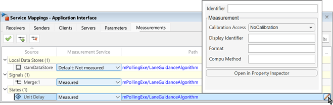
In some of the tabs, not all properties are shown in the table. To update these
additional properties for individual entries, click the pencil icon  at the end of the table entry.
Tip
To close the dialog box, click anywhere outside the dialog box.
Click Open in Property Inspector in the dialog box to open the Property Inspector.
You can open the dialog box for any table entry (and use it to open the Property Inspector for the selected entry), but in some tabs of the Service Mappings editor, there are no additional properties to configure in the dialog box itself.
Property Inspector
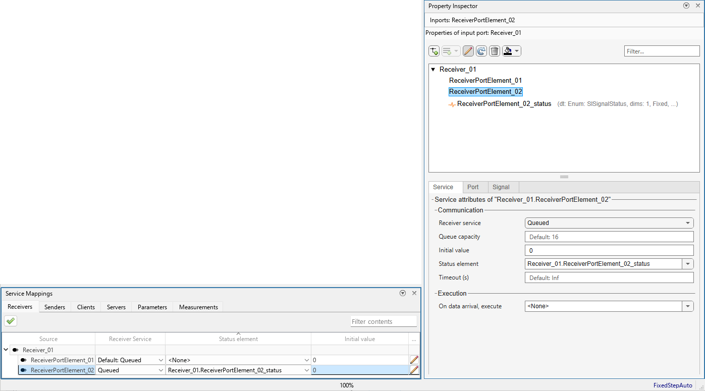
Use the Property
Inspector to view and configure the complete set of service interface definitions
of any specific model element. When you select an entry from the table, the Property
Inspector is automatically synchronized to display the properties of the model element that
corresponds to the selected table entry. If the Property Inspector is not open, you can open
it by clicking the pencil icon at the end of the table entry, and then clicking
Open in Property Inspector in the dialog box that opens.
Examples
Open model
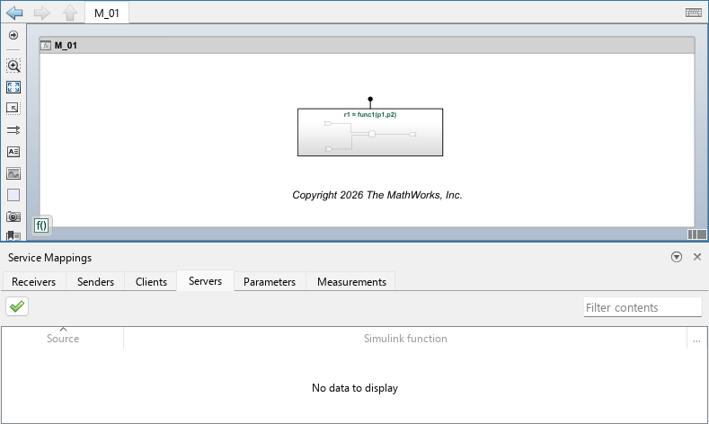
M_01.serviceMapDemo = "M_01"; open_system(serviceMapDemo)Open the Service Mappings editor and select the Servers tab.
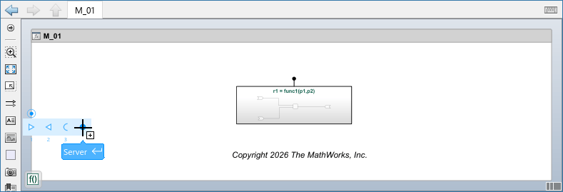
Add a Server port block to the model: Hover over the left border of the canvas. In the menu that opens, select the fourth (rightmost) option.
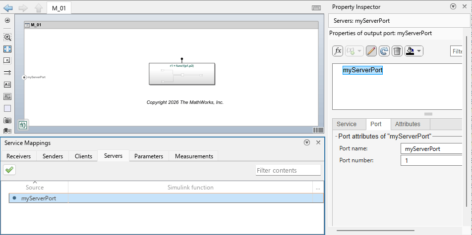
Rename the port to
myServerPort.In the Servers tab of the Service Mappings editor, locate the entry for the new Server port block. Make sure the port is selected, and open the Property Inspector.
In the Property Inspector click the Add a new function button
 to add a server function prototype to the Server
port block. A new child node appears under
to add a server function prototype to the Server
port block. A new child node appears under myServerPortin the Property Inspector with the default function prototype,y=f1(u). Double-click the new child function and revise its prototype tor1 = func1(p1,p2)to match the prototype of the function in the Simulink Function block in your model.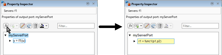
In the Service Mappings editor, the Server port block now has a foldable child element. In the Simulink function list, select
func1to map Simulink functionfunc1to the new child element ofmyServerPort.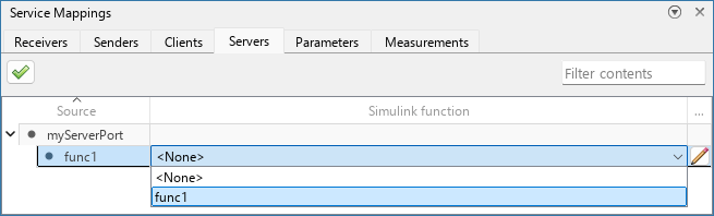
Related Examples
Service Interface Categories
This table shows the available service interface categories:
| Category | Purpose | Related Example |
|---|---|---|
| Receivers | Map signals of In Bus Element blocks to incoming communication service definitions. | Configure Root-Level Model Ports with Receiver and Sender Service Interface Definitions |
| Senders | Map signals of Out Bus Element blocks to outgoing communication service definitions. | Configure Root-Level Model Ports with Receiver and Sender Service Interface Definitions |
| Clients | Map function callers in your model to client service interface definitions. These definitions determine how the function callers invoke functions exported by other models in the system. | Configure Simulink Functions and Function Callers with Client and Server Service Interface Definitions |
| Servers | Map exported functions in your model to server service interfaces to allow other models to invoke these functions. | Configure Simulink Functions and Function Callers with Client and Server Service Interface Definitions |
| Parameters | Map model parameters to calibration service definitions. | Configure Model Parameters with Tuning Service Interface Definitions |
| Measurements | Map model signals, data stores, and states to measurement service definitions. | Configure Model Signals, States, and Data Stores with Measurement Service Interface Definitions |
More About
To validate the service mapping configuration, click the Validate Service Mappings
button  .
.
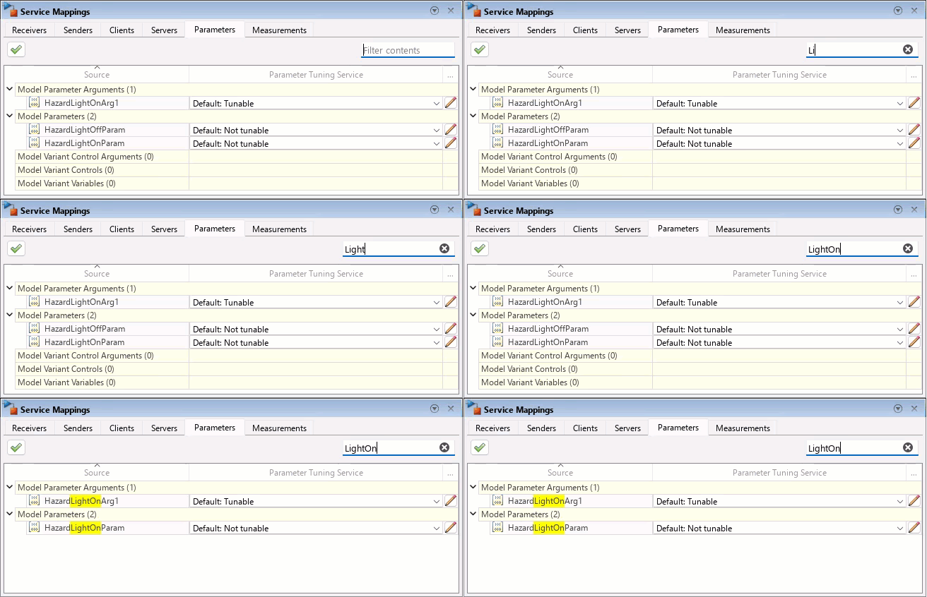
Use the Filter contents field to filter the table to display only entries that contain the text you specify, in any of its columns.
Version History
Introduced in R2026b

