Control Volume System
Constant volume open thermodynamic system with heat transfer

Libraries:
Powertrain Blockset /
Propulsion /
Combustion Engine Components /
Fundamental Flow
Description
The Control Volume System block models a constant volume open thermodynamic system with heat transfer. The block uses the conservation of mass and energy, assuming an ideal gas, to determine the pressure and temperature. The block implements an automotive-specific Constant Volume Pneumatic Chamber block that includes thermal effects related to the under hood of passenger vehicles. You can specify heat transfer models:
Constant
External input
External
                                wall convection
You can use the Control Volume System block to represent engine components that contain volume, including pipes and manifolds.
Thermodynamics
The Control Volume System block implements a constant volume chamber containing an ideal gas. To determine the rate changes in temperature and pressure, the block uses the continuity equation and the first law of thermodynamics.
The block uses this equation for the volume-specific enthalpy.
The equations use these variables.
Mass flow rate at port | |
| qi | Heat flow rate at port |
| Vch | Chamber volume |
| Pvol | Absolute pressure in the chamber |
| R | Ideal gas constant |
| cv | Specific heat at constant volume |
| Tvol | Absolute gas temperature |
| Qwall | Wall heat transfer rate |
| hvol | Volume-specific enthalpy |
| cp | Specific heat capacity |
Mass Fractions
The Control Volume Source block is part of a flow network. Blocks in the network determine the mass fractions that the block will track during simulation. The block can track these mass fractions:
O2— OxygenN2— NitrogenUnburnedFuel— Unburned fuelCO2— Carbon dioxideH2O— WaterCO— Carbon monoxideNO— Nitric oxideNO2— Nitrogen dioxidePM— Particulate matterAir— AirBurnedGas— Burned gas
Using the conservation of mass for each gas constituent, this equation determines the rate change:
The equations use these variables.
| Vch | Chamber volume |
| Pvol | Absolute pressure in the chamber |
| R | Ideal gas constant |
| Tvol | Absolute gas temperature |
| yi,j | I-th port mass fraction for j = O2, N2, unburned fuel, CO2, H2O, CO, NO, NO2, PM, air, and burned gas |
| yvol,j | Control volume mass fraction for j = O2, N2, unburned fuel, CO2, H2O, CO, NO, NO2, PM, air, and burned gas |
Mass flow rate for i = O2, N2, unburned fuel, CO2, H2O, CO, NO, NO2, PM, air, and burned gas |
External Wall Convection Heat Transfer Model
To calculate the heat transfer, you can configure the Control Volume Source block to calculate the heat transfer across the wall of the control volume.

The block implements these equations to calculate the heat transfer, Q1, from the internal control volume gas to the internal wall depth, Dint_cond.
The block implements these equations to calculate the heat transfer, Q2, from the external wall depth, Dext_cond to the external gas.
This equation expresses the heat stored in the thermal mass.
The block determines the interior convection heat transfer coefficient using a lookup table that is a function of the average mass flow rate.
The equations use these variables.
| Q1 | Heat flow from the internal gas to a specified wall depth |
| Q1,conv | Heat flow convection from the internal gas to the internal wall |
| Q1,cond | Conduction heat transfer rate |
| Q2 | Heat transfer rate |
| Q2,conv | Convection heat transfer |
| Q2,cond | Heat flow conduction from the external middle portion of the wall to the external wall |
| Qmass | Heat stored in thermal mass |
| hint | Internal convection heat transfer coefficient |
| xint | Internal mass flow rate breakpoints |
| Aint_conv | Internal flow convection area |
| Tint_gas | Temperature of the gas inside the chamber |
| Tw_int | Temperature of the inside wall of the chamber |
| kint | Internal wall thermal conductivity |
| Aint_cond | Internal conduction area |
| Dint_cond | Internal wall thickness |
| hext | External convection heat transfer coefficient |
| xext | External velocity breakpoints |
| Aext_conv | External convection area |
| Text_gas | External gas temperature |
| Tw_ext | Temperature of the external wall of the chamber |
| kext | External wall thermal conductivity |
| Aext_cond | External conduction area |
| Dext_cond | External wall thickness |
| Tmass | Temperature of the thermal mass |
| cp_wall | Wall heat capacity |
| mwall | Thermal mass |
| Flwspd | External flow velocity |
Average internal mass flow rate |
Power Accounting
For the power accounting, the block implements these equation based on the number of inlet and outlet ports.
| Bus Signal | Description | Equations | ||
|---|---|---|---|---|
|
|
| Port | qi |
|
|
| Heat transfer rate from wall to control volume | -Qwall | |
|
|
| Rate of heat stored in the control volume | ||
For example, if you configure your block with 3 input ports and 2 outlet ports, the block implements these equations
| Bus Signal | Description | Equations | ||
|---|---|---|---|---|
|
|
| Inlet port 1 heat flow | q1 |
| Inlet port 2 heat flow | q2 | ||
| Inlet port 3 heat flow | q3 | ||
| Outlet port 4 heat flow | q4 | ||
| Outlet port 5 heat flow | q5 | ||
|
|
| Heat transfer rate from wall to control volume | -Qwall | |
|
|
| Rate of heat stored in the control volume | ||
Examples
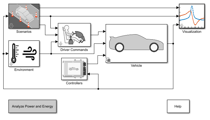
Build Conventional Vehicle Model
Build a vehicle with an internal combustion engine using the conventional vehicle reference application.
Ports
Input
Output
Parameters
References
[1] Heywood, John B. Internal Combustion Engine Fundamentals. New York: McGraw-Hill, 1988.
Extended Capabilities
Version History
Introduced in R2017a
See Also
Flow Restriction | Heat Exchanger | Constant Volume Pneumatic Chamber (Simscape)