Polarization Analysis of X-band Microstrip Patch Antenna
This example shows how to perform polarization analysis on a microstrip patch antenna with the air substrate. The dimensions of this antenna are referenced from [1] for the center frequency of 10.35 GHz. In most basic form, a microstrip patch antenna consists of a radiating patch on one side of a dielectric substrate and a ground plane on the other side. Microstrip patch antennas radiate primarily as wide open-open half-wave microstrip resonators. The length L of the rectangular patch for the fundamental excitation mode is slightly less than /2. For a good antenna performance, a thick dielectric substrate having a low dielectric constant is usually desired since it provides a larger bandwidth and a well-defined beam. A rectangular microstrip patch antenna normally radiates a linearly polarized wave with about 6-7 dBi gain at broadside. Higher gains (up to 10 dBi) can be achieved by using different means including large patch heights and parasitic patches.
Define Parameters
Define the operating frequency and dimensions for the microstrip patch antenna.
freq = 10.35e9;
patchLength = 12e-3;
patchWidth = 17.73e-3;
patchHeight = 1.56e-3;
lengthgp = 55e-3;
widthgp = 55e-3;
feedoffset = [2.9e-3 0];
Create Antenna
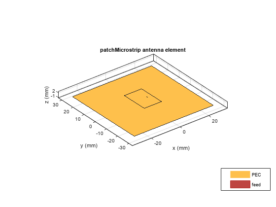
Use the parameters defined in the previous section to create a microstrip patch antenna.
ant = patchMicrostrip(Length=patchLength,Width=patchWidth,...
    Height=patchHeight,GroundPlaneLength=lengthgp,...
    GroundPlaneWidth=widthgp,FeedOffset=feedoffset);
figure
show(ant)
Co-Polarization Pattern in H-plane
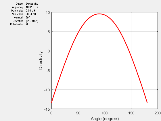
The plane, which contain the electric-field vector and the direction of maximum radiation, is known as the E-plane [2] for linearly-polarized antennas. The E-plane is the xz-plane in the present case it is determined by the feed shift in the x-direction, but has generally nothing in common with the relative patch dimensions in the figure. The plane, which contains the magnetic-field vector and the direction of maximum radiation, is known as the H-plane for linearly-polarized antennas. The H-plane in the present case is the yz-plane. Co-polarization is the intended antenna polarization. In the H-plane, the intended polarization is the electric-field component in the x- direction (which coincides with azimuthal component). The plot given below shows the directivity of this azimuthal component in the H-plane (the co-polarization radiation pattern). As expected, the co-polarization pattern drops sharply close to the ground plane, which reflects the boundary condition of no tangential field on the metal ground plane.
pattern(ant,freq,90,0:1:180,CoordinateSystem="rectangular",...
    Polarization='H');
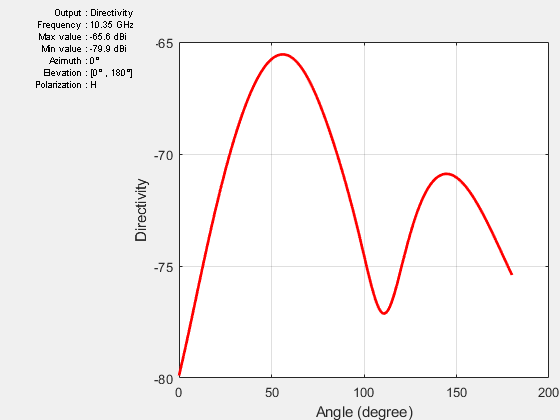
Cross-Polarization Pattern in H-plane
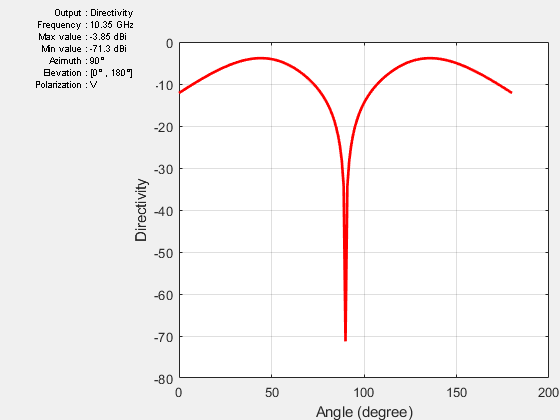
Cross-polarization is the undesired antenna polarization. Cross polarized electric-field component is perpendicular to the co-polarized component. In the H-plane, the cross-polarization is given by the combined electric-field components in the y- and z-directions, which is the elevation electric-field component. The difference between the co- and cross-polarizations is called the polarization isolation. The plot given below shows the directivity of the cross-polarized E-field in the H-plane (cross-polarization radiation pattern). As expected, there is a null at zenith.
pattern(ant,freq,90,0:1:180,CoordinateSystem="rectangular",...
    Polarization='V');
Co-Polarization Pattern in E-plane
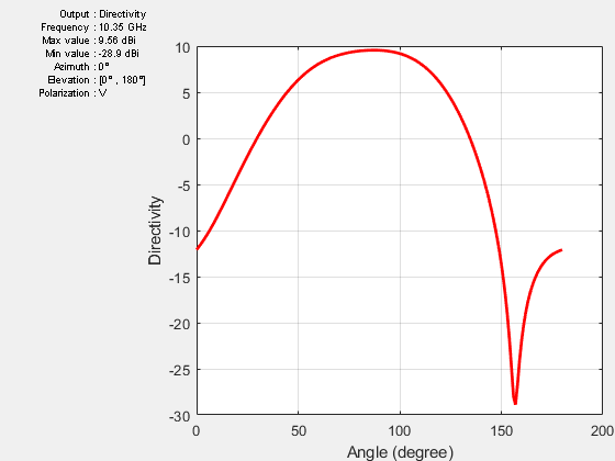
In the E-plane, the intended polarization is given by the combined electric-field components in the x- and z-directions, which is the elevation electric-field component. The plot given below shows the directivity of the co-polarized E-field in the E-plane (co-polarization radiation pattern). As expected, the pattern is not symmetric due to the feed effect.
pattern(ant,freq,0,0:1:180,CoordinateSystem="rectangular",...
    Polarization='V');
Cross-Polarization Pattern in E-plane
In the E-plane, the cross-polarization is given by the electric-field component in the y-direction, which is the azimuthal electric-field component. The plot given below shows the directivity of the cross-polarized E-field in the E-plane (cross-polarization radiation pattern). As expected, the pattern indicates a very low cross-polarization.
pattern(ant,freq,0,0:1:180,CoordinateSystem="rectangular",...
    Polarization='H');
Conclusion
The overall behavior of the antenna matches well with the results published in [1].
Reference
[1] D. Guha, S. Chattopadhya, J. Y. Siddiqui, "Estimation of gain enhancement replacing PTFE by air substrate in a microstrip patch antenna [Antenna Designer's Notebook]," IEEE Antennas and Propagation Magazine, vol.52, no.3, pp.92-95, June 2010.
[2] C. A. Balanis, 'Antenna Theory. Analysis and Design,' p.33, Wiley, New York, 3rd Edition, 2005.