このページの内容は最新ではありません。最新版の英語を参照するには、ここをクリックします。
PCB スタックを使用したマイクロストリップ パッチ アンテナの設計バリエーション
pcbstack を使用して、基本パッチ アンテナ、寄生パッチ アンテナ、直接結合パッチ アンテナ、CP パッチ アンテナを設計します。
パラメーターを設定します。
vp = physconst("lightspeed");
f = 850e6;
lambda = vp./f;
基本パッチ アンテナの設計
パッチおよびグランドプレーンの長さと幅を設定します。
Lp = lambda(1)/2;
Wp = lambda(1)/2;
Lgp = 0.75.*lambda(1);
Wgp = 0.75.*lambda(1);
h = 2.e-3;
p1 = antenna.Rectangle(Length=Lp, Width=Wp, NumPoints=30);
p2 = antenna.Rectangle(Length=Lgp, Width=Wgp);
d1 = dielectric("Air");
PCB スタックのプロパティを定義します。
basicPatch = pcbStack;
basicPatch.Name = "Basic Patch";
basicPatch.BoardThickness = h;
d1.Thickness = h;
basicPatch.BoardShape = p2;
basicPatch.Layers = {p1,d1,p2};
basicPatch.FeedLocations = [-lambda(1)/8 0 1 3];
figure
show(basicPatch)
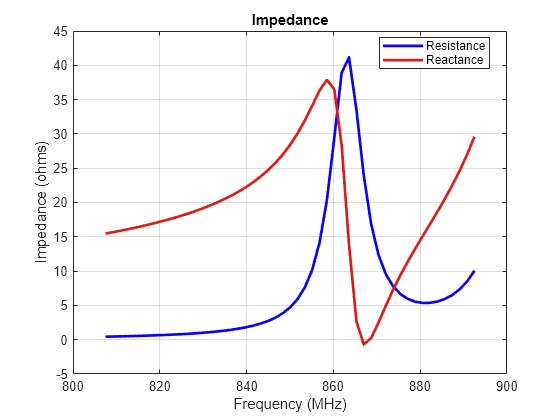
基本パッチ アンテナのインピーダンスをプロットします。
freq1 = linspace(f(1)-0.05*f(1),f(1) + 0.05*f(1),51);
figure
impedance(basicPatch,freq1)
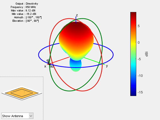
基本パッチ アンテナの放射パターンをプロットします。
figure
pattern(basicPatch,f(1))
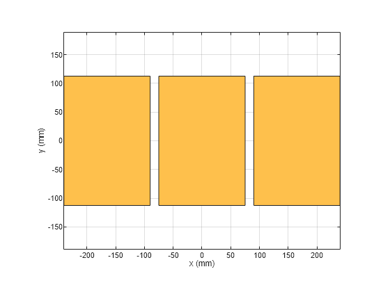
寄生パッチ アンテナの設計
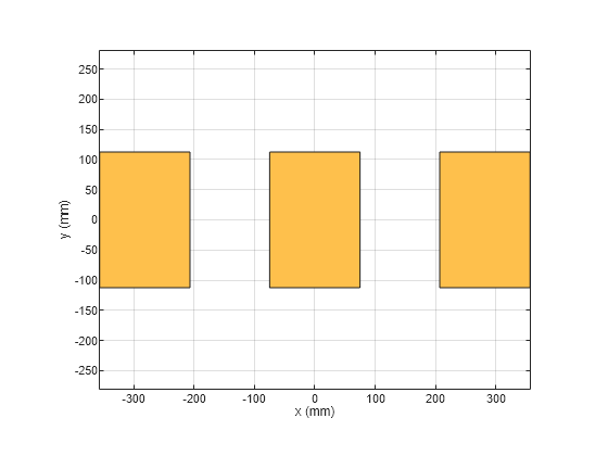
パッチの寸法を設定します。
L = 0.15;
W = 1.5*L;
stripL = L;
gapx = 0.015;
gapy = 0.01;
r1 = antenna.Rectangle(Center=[0 0], Length=L, Width=W);
r2 = antenna.Rectangle(Center=[L/2+stripL/2+gapx 0], Length=stripL,...
    Width=W, NumPoints=[2 20 2 20]);
r3 = antenna.Rectangle(Center=[-L/2-stripL/2-gapx 0], Length=stripL,...
    Width=W, NumPoints=[2 20 2 20]);
r = r1 + r2 + r3;
figure
show(r)
グランドプレーンの寸法を設定します。
Lgp = 0.55;
Wgp = 0.4;
g1  = antenna.Rectangle(Center=[0 0], Length=Lgp, Width=Wgp);
PCB スタックのプロパティを定義します。中央の放射体に給電して PCB スタックを作成します。
parasitic_patch = pcbStack;
parasitic_patch.BoardShape = g1;
parasitic_patch.BoardThickness = 0.007;
parasitic_patch.Layers = {r,g1};
parasitic_patch.FeedLocations = [(L)/4 0 1 2];
figure
show(parasitic_patch)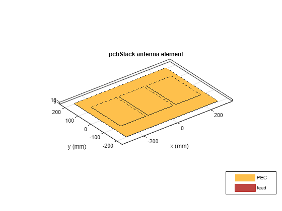
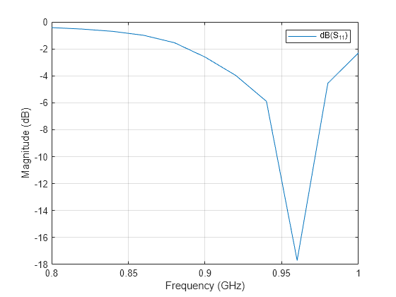
寄生パッチ アンテナの S パラメーターをプロットします。
s = sparameters(parasitic_patch,linspace(0.8e9,1e9,11));
figure
rfplot(s)
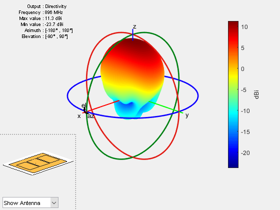
寄生パッチ アンテナの放射パターンをプロットします。
figure
pattern(parasitic_patch,0.896e9)
直接結合パッチ アンテナの設計
r2 = copy(r1);
r2.Center = [lambda/1.25 0];
r3 = copy(r1);
r3.Center = [-lambda/1.25 0];
r = r1+ r2 + r3;
figure
show(r)
セクションをストリップ接合します。
r4 = antenna.Rectangle(Length=0.65*lambda, Width=0.02*lambda,...
    Center=[lambda/2 0], NumPoints=[20 2 20 2]);
r5 = copy(r4);
r5.Center = [-lambda/2 0];
s = r + r4 + r5;
figure
show(s)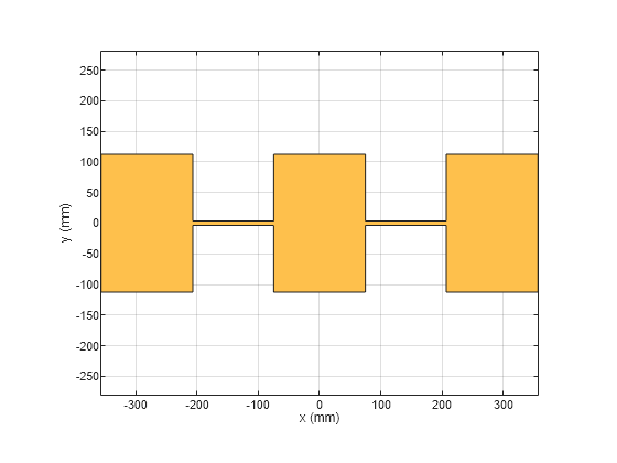
PCB スタックのプロパティを定義します。
g1.Length = 0.8;
series_patch = pcbStack;
series_patch.BoardShape = g1;
series_patch.Layers = {s,g1};
series_patch.FeedLocations = [L/4 0 1 2];
figure
show(series_patch)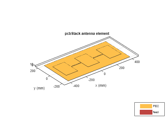
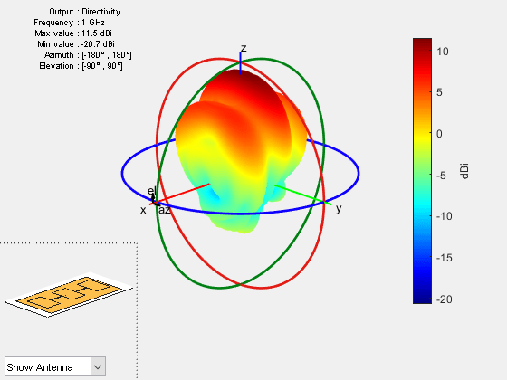
直接結合パッチ アンテナの 1 GHz における放射パターンをプロットします。
figure
pattern(series_patch,1e9)
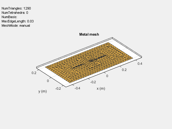
最大エッジ長 0.03 m を使用してアンテナをメッシュ化します。
figure
mesh(series_patch, MaxEdgeLength=0.03)
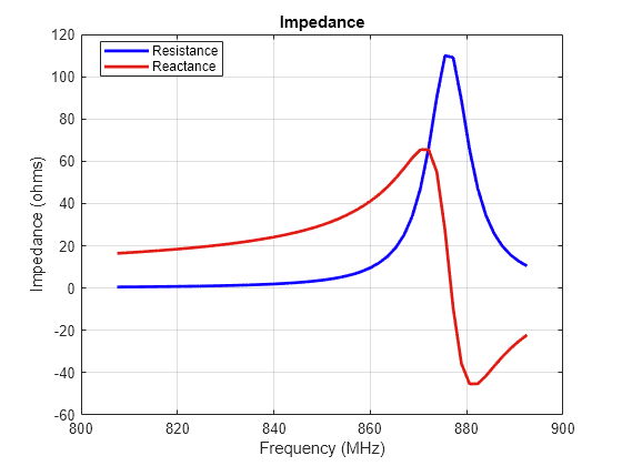
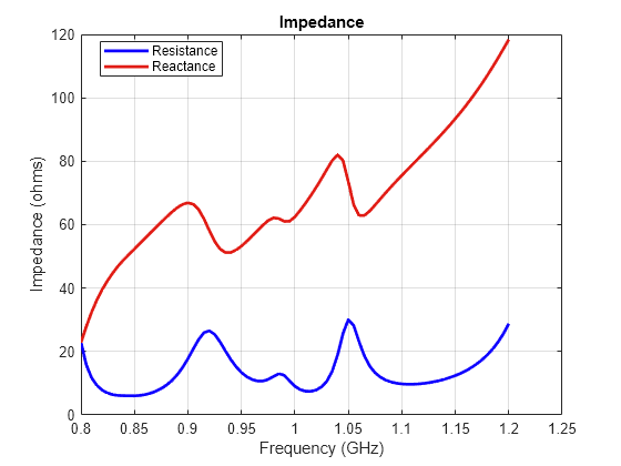
0.8 GHz から 1.2 GHz の周波数範囲における直接結合パッチ アンテナのインピーダンスをプロットします。
figure
impedance(series_patch,linspace(0.8e9,1.2e9,81))
円偏波パッチの設計 - 角の切り欠き
パッチおよびグランドプレーンの長さと幅を設定します。
Lp = lambda(1)/2;
Wp = lambda(1)/2;
Lgp = 0.75.*lambda(1);
Wgp = 0.75.*lambda(1);
h = 2.e-3;
パッチの基本形状を作成します。
p1 = antenna.Rectangle(Length=Lp, Width=Wp, NumPoints=20);
矩形の角に切り欠きを設けます。
Lcorner = 0.25*Lp;
Wcorner = 0.25*Wp;
cornerCenter1 = [-Lp/2,Wp/2 0];
cornerCenter2 = [Lp/2,-Wp/2 0];
pcorner1 = antenna.Rectangle(Length=Lcorner, Width=Wcorner);
pcorner1 = rotateZ(pcorner1,45);
pcorner1 = translate(pcorner1,cornerCenter1);
pcorner2 = antenna.Rectangle(Length=Lcorner, Width=Wcorner);
pcorner2 = rotateZ(pcorner2,45);
pcorner2 = translate(pcorner2,cornerCenter2);
pradiator = p1 - pcorner1 - pcorner2;
グランドプレーンの形状を作成します。
p2 = antenna.Rectangle(Length=Lgp, Width=Wgp);
誘電体層を定義します。
d1 = dielectric("Air");円偏波パッチ用の PCB スタックのプロパティを定義します。
truncatedCornerPatch = pcbStack;
truncatedCornerPatch.Name = "Basic Patch";
truncatedCornerPatch.BoardThickness = h;
d1.Thickness = h;
truncatedCornerPatch.BoardShape = p2;
truncatedCornerPatch.Layers = {pradiator,d1,p2};
truncatedCornerPatch.FeedLocations = [-lambda(1)/8 0 1 3];
figure
show(truncatedCornerPatch)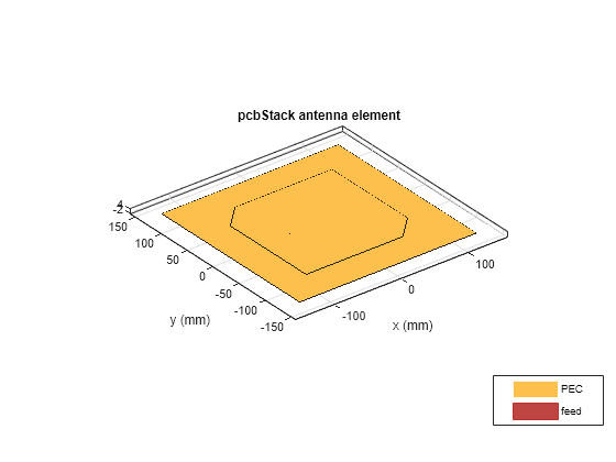
円偏波アンテナのインピーダンスをプロットします。
figure
impedance(truncatedCornerPatch,freq1)