X-Drive Robot Navigation with VEX V5 GPS Sensor
This example shows how to use a VEX® V5 GPS Sensor with Simulink® Coder™ Support Package for VEX V5 Robot Brain and control the robot to follow a set of waypoints.
Prerequisites
If you are new to Simulink, watch the Simulink Quick Start video.
Complete the Getting Started with Simulink Coder Support Package for VEX EDR V5 Robot Brain example.
Required Hardware
To run this example, you need these hardwares:
VRC Field
V5 Brain
Controller and radio
4x Smart motors (18:1)
4x Omni wheels
V5 GPS sensor
V5 GPS field strips
Battery
Connecting the Hardware
1. Assemble a X-Drive robot. Here is a sample robot image.

2. Mount a GPS sensor on the robot. Note down the position (X, Y) and heading (clockwise positive) of the sensor relative to the center of robot.
3. Connect and pair a Controller with V5 Radio.
4. Setup a V5 field. For information, see Mounting the GPS Field Code Strips
5. Connect these ports.
Port 1: Front-right Smart Motor
Port 2: Back-left Smart Motor
Port 3: Front-left Smart Motor
Port 4: Back-right Smart Motor
Port 11: V5 GPS Sensor
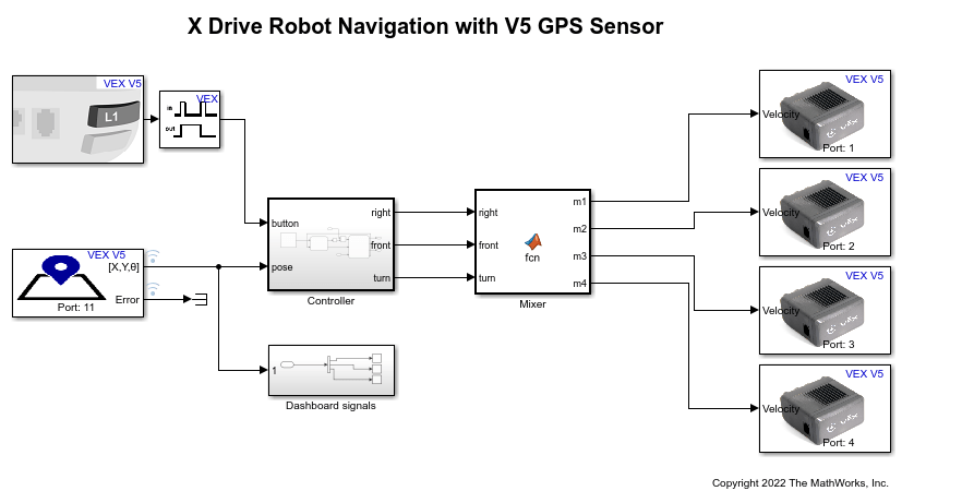
Model
Simulink® Coder™ Support Package for VEX EDR V5 Robot Brain provides a preconfigured model that you can use to get the robot to follow a set of waypoints using the Differential (Tank) Drive block.
Open the vexv5_xdrive_gps_nav model.
Set Parameters in Simulink Model
1. In the Simulink model, double-click the V5 GPS Sensor block to open the block parameter dialog box.
2. Set the position and orientation of GPS Sensor on the robot. Click Visualize to verify the configuration.

Note: "Initial Robot Pose" is optional. It is used for setting the sensor output, if GPS field strips are not visible initially.
Description of Stateflow chart and Mixer Model
Controller subsystem
This subsystem contains:
A set of pose waypoints (X, Y, Theta)
Waypoint picker
Waypoint follower
Waypoint picker choses one of the waypoints and sends it to the Waypoint follower block. Additionally, whenever a waypoint is complete, it switches to the next one.
Waypoint follower takes the waypoint pose (X, Y, Theta) and provides the required body frame velocities (front, right and turn velocity). This subsystem converts the position error (desired X, Y - Current X, Y) in field frame to body frame. Then, it applies proportional controllers over the X_body and Y_body errors. When a waypoint is complete, a message is sent to waypoint picker block.
Mixer
The controller outputs right, front, and turn velocities. But there are four independent motors to control.
Assume that forward motion, sideways motion, and turning are independent of each other.
To turn the robot in place, all the 4 motors must spin in the same direction.
To move the robot forward without any sideways or turning motion, front left and front right motors must spin in opposite directions which moves the robot forward. Back motors does the same.
For moving the robot sideways, right motors must spin in opposite directions. Similar to forward motion.
Combine the above conditions to arrive at,

Simulate the Model
1. Open the preconfigured Simulink model.
2. To simulate the model, go to the Simulation tab of the Simulink model window and click Run. The lower-left corner of the model window displays the status while Simulink prepares to run the model on the host computer.
3. Press Start button in the Simulink model to start the robot. This is a sample GIF image of the simulation.

Build and Download the Simulink Model
Open the preconfigured model or create a Simulink model, build the model, and download it to the VEX V5 Robot Brain.
1. Connect the V5 Robot Brain to your computer using the USB cable.
2. Open the Simulink model. If you are using the preconfigured model, go to step 5.
3. Click Modeling and press CTRL+E to open Configuration Parameters dialog box.
4. In the Configuration Parameters dialog box, navigate to the Hardware Implementation pane.
Set the Hardware board to VEX V5 Robot Brain.
In the Target Hardware Resources section, set the Build options to Build, load and run to automatically download the binary file on to the connected V5 Robot Brain.
5. Click Hardware and then click Build, Deploy & Start. The model is deployed to the V5 Robot Brain. This action builds, downloads, and runs the model as a standalone application on the VEX V5 Robot Brain device.
The waypoints x, y and theta are displayed on the user interface of the robot. For information on creating touch screen controls, see Creating Touch Screen Controls and Displays for VEX V5 Robot Brain. Press L1 button on controller to start the robot. The robot moves to the first waypoint and stops. Pressing the start L1 button again moves the robot to the next waypoint.
See Also
You can also select a web site from the following list:
Americas
- América Latina (Español)
- Canada (English)
- United States (English)
Europe
- Belgium (English)
- Denmark (English)
- Deutschland (Deutsch)
- España (Español)
- Finland (English)
- France (Français)
- Ireland (English)
- Italia (Italiano)
- Luxembourg (English)
- Netherlands (English)
- Norway (English)
- Österreich (Deutsch)
- Portugal (English)
- Sweden (English)
- Switzerland
- United Kingdom (English)