Navigating VEX Robot with Wheel Odometry in Gazebo Simulator
This example shows how to simulate a robot moving from one point to another using wheel encoders. This example has a model of VEX® robot created for Gazebo simulator (along with a virtual world). The robot's control algorithm is modelled as a Stateflow® chart in Simulink®. Simulink reads data from sensors and writes commands to motors in Gazebo using Gazebo co-simulation blocks.

Set Up Gazebo Simulation Environment
To run this example, download and set up the preconfigured Virtual Machine with ROS and Gazebo. For more information, see Set Up Gazebo Simulation Environment. In the Setup Gazebo Simulation Environment topic, perform the steps listed in these topics.
Simulink Model
1. Open the preconfigured vexv5_gzsim_odometry Simulink example model.
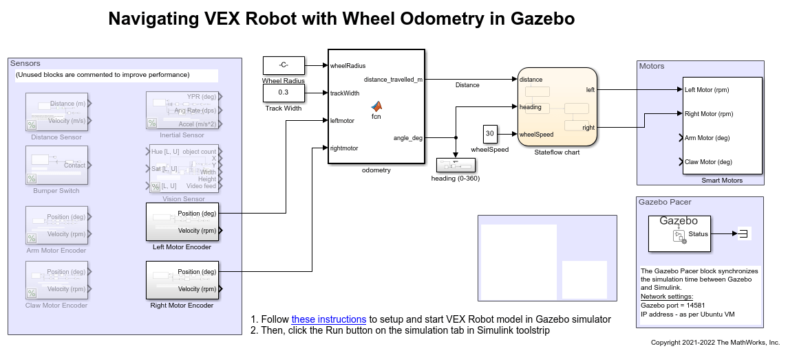
2. Navigate to VEX V5 Robot interface/Gazebo Simulation Interface subsystem and Open Gazebo Pacer block.
3. Click on Configure Gazebo network and simulation settings link. Enter the Virtual Machine IP Address. Set the Port to 14581.
4. Click Test connection to verify the connection to Gazebo model. Click Ok and close the block dialog.

Program Logic
The control algorithm of the robot is modeled in the vexv5_gzsim_odometry > Stateflow chart Stateflow chart. Double-click the chart to view the logic.
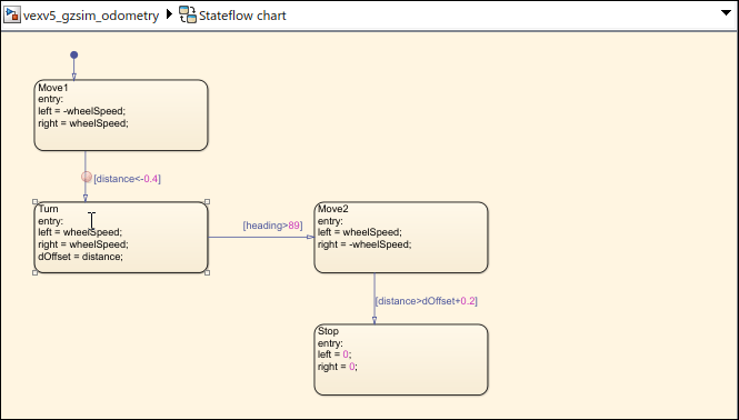
Distance and heading change are computed from encoders on the wheel. The Stateflow chart first drives the robot until a certain distance is crossed. Then it turns until angle is about 90 degrees. Similar transitions are repeated until the robot reaches target position.
Simulate Model
In the preconfigured Simulink model, on the Simulation tab, click Run to simulate the model.
Other Things to Try
Navigating with encoders can be erroneous due to wheel slippage. Compare the distance reading obtained from encoders against another reference such as distance to wall, IMU heading, and so on.
See Also
You can also select a web site from the following list:
Americas
- América Latina (Español)
- Canada (English)
- United States (English)
Europe
- Belgium (English)
- Denmark (English)
- Deutschland (Deutsch)
- España (Español)
- Finland (English)
- France (Français)
- Ireland (English)
- Italia (Italiano)
- Luxembourg (English)
- Netherlands (English)
- Norway (English)
- Österreich (Deutsch)
- Portugal (English)
- Sweden (English)
- Switzerland
- United Kingdom (English)