Implement Image Inversion Algorithm Using Raspberry Pi
This example shows how to use the V4L2 Video Capture and the SDL Video Display blocks from the Raspberry Pi® block library to implement an image inversion algorithm with a Simulink® model, and to run the model on Raspberry Pi hardware.
Introduction
Black and white image inversion refers to an image processing technique where light areas are mapped to dark, and dark areas are mapped to light. In other words, after image inversion black becomes white and white becomes black. An inverted black and white image can be thought of as a digital negative of the original image.
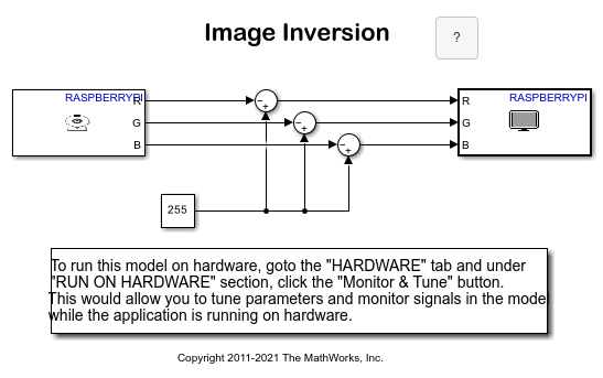
In this example, the inversion algorithm is be applied to the red (R), green (G) and blue (B) components of an image captured from a USB camera creating a color digital negative effect. The R, G and B components of the image are represented as uint8 values. That is, the range of the values that any of the color components can take is from 0 to 255. Assuming that the intensity value at position  of the image is
  , the inversion mapping is defined by
  .
.
Prerequisites
Complete the Get Started with Simulink Support Package for Raspberry Pi Hardware example.
Required Hardware
To run this example you will need the following hardware:
Raspberry Pi hardware
(Optional) To display the output video on an external monitor you will need the following:
HDMI or composite television, or a monitor with DVI or HDMI input, and appropriate cables
USB mouse and keyboard
Task 1 - Connect Camera
In this task, you will connect a USB camera or a Raspberry Pi camera module to your Raspberry Pi hardware and check if the camera was detected properly by the Linux® kernel.
1. If you have a USB camera:
Connect the USB camera to one of the USB ports on your Raspberry Pi board. Note that some cameras may draw too much power and may require a powered USB hub for proper operation.
If you have a Raspberry Pi camera module:
Connect the camera module to the Raspberry Pi board using a CSI cable by following the manufacturer's instructions.
Activate the Raspberry Pi camera module V4L2 kernel driver by executing the following commands on the MATLAB® prompt:
r = raspberrypi;
system(r,'/sbin/modprobe bcm2835_v4l2')
2. Check if the camera is recognized by the Linux kernel by executing the following command on the MATLAB prompt:
system(r,'ls -al /dev/video*')
Typical output will be:
crw-rw---T+ 1 root video 81, 0 Dec 16 14:43 /dev/video0
Make sure that the video device file name displayed above matches to the 'Device name' parameter specified on the V4L2 Video Capture block mask. In this example, the 'Device name' should be set to '/dev/video0'.
Task 2 - Signal Monitoring and Parameter Tuning
Perform Monitor and Tune action on the image inversion model. The image is captured from the USB camera connected to the Raspberry Pi hardware and the results of the image inversion is sent back to the host computer to be displayed by the on SDL Video Display block.
1. Open the raspberrypi_inversion Simulink model.
2. Select Apps > Run on Hardware Board. Review the parameters on the page that opens and make sure that the connection parameters for your Raspberry Pi board are correct.
3. On the Hardware tab of the Simulink model, in the Mode section, select Run on board and then click Monitor & Tune to run the model on Raspberry Pi hardware.
4. Observe the display of inverted images on the host computer.
5. While the model is running, double click on the Constant block and change the Constant value from 255 to 120, for example. Observe the resulting image effect.
6. Press the Stop button on the model to stop model execution.
Task 3 - Configure and Run Image Inversion Model as Standalone Application
In this task, you will connect a monitor to Raspberry Pi hardware. The video captured from the USB camera will be inverted by the model running on Raspberry Pi hardware and displayed on the monitor connected to Raspberry Pi hardware.
1. Using appropriate cables, connect a monitor or television to the Raspberry Pi hardware. The monitor, once connected, will display the Linux desktop.
2. Connect a USB mouse and a keyboard to the Raspberry Pi hardware's USB ports. Once connected, login to Linux desktop as you would to any Linux® computer.
3. Open the Image Inversion model.
4. Select Apps > Run on Hardware Board > Options.... Review the parameters on the page that opens and make sure that the connection parameters for your Raspberry Pi board are correct.
5. On the Hardware tab of the Simulink model, in the Mode section, select Run on board and then click Build, Deploy & Start to run the model on the Raspberry Pi hardware. On the monitor connected to Raspberry Pi hardware, you will see a window displaying inverted images.
6. Stop the model running on the Raspberry Pi hardware by executing the following on the MATLAB command line
stopModel(r,'raspberrypi_inversion');
Other Things to Try
Change the model to use a different constant value for each color component. Then, independently change the value of each of the constants to get a wider range of imaging effects.
You can also select a web site from the following list:
Americas
- América Latina (Español)
- Canada (English)
- United States (English)
Europe
- Belgium (English)
- Denmark (English)
- Deutschland (Deutsch)
- España (Español)
- Finland (English)
- France (Français)
- Ireland (English)
- Italia (Italiano)
- Luxembourg (English)
- Netherlands (English)
- Norway (English)
- Österreich (Deutsch)
- Portugal (English)
- Sweden (English)
- Switzerland
- United Kingdom (English)