Define Custom Board and Reference Design for Microchip Workflow
This example shows how to define and register a custom board and reference design for a blinking LED model in the Microchip workflow of the HDL Workflow Advisor. You use a SmartFusion2® board, but you can define and register a custom board or a custom reference design for other Microchip platforms.
Requirements
To run this example, you need access to:
A Microchip Libero SoC Design Suite. For a list of supported versions, see HDL Language Support and Supported Third-Party Tools and Hardware.
A Microchip SmartFusion2 development board with the accessory kit.
HDL Coder™ Support Package for Microchip FPGA and SoC Devices.
Set Up SmartFusion2 Board
To familiarize yourself with the features of the SmartFusion2 board, see the SmartFusion2 Board Reference Manual. To set up your SmartFusion2 board, follow these steps.
1. Install the USB COM port device drivers on your computer.
2. Connect the shared UART/JTAG USB port on the SmartFusion2 board to your computer.
3. Download and install HDL Coder Support Package for Microchip FPGA and SoC Devices. To access the hardware support package, in the Home tab of your MATLAB session, click Add-Ons and then click Get Hardware Support Packages.
4. Set up the Microchip Libero tool path by using the hdlsetuptoolpath function. For example, to set up the Microchip Libero SoC tool, specify ToolName as Microchip Libero SoC and ToolPath as your installed Libero executable path.
hdlsetuptoolpath('ToolName', 'Microchip Libero SoC', ...
    'ToolPath', 'C:\Microsemi\Libero_SoC_v2022.1\Designer\bin\libero.exe');
Create and Export Custom Reference Design by Using Microchip Libero SoC
A reference design captures the complete structure of an SoC design, defining the different components and their interconnections. Use the HDL Coder SoC workflow in the HDL Workflow Advisor to generate an IP core that integrates with the reference design and program an SoC board. This figure shows the relationship between a reference design, an HDL IP core, and an SoC board.

To create and export a reference design by using the Microchip Libero Tool environment, follow these steps.
1. Create a microcontroller subsystem (MSS) based Microchip Libero SoC RTL project by using the SmartFusion2 board settings as specified in this figure and then click Next. This Libero project is required only to generate SmartFusion2 configuration files.

2. In the Design Template window, select Create a microcontroller (MSS) based design and then click Next.

3. Click Finish to create a smart design containing the SmartFusion2 MSS component. To configure the MSS, double-click SmartFusion2_MSS_MSS IP.

4. Clear the check boxes from the peripherals that you do not want to use. Double-click MDDR and select this configuration for the AXI Master interface.

5. Double-click Reset Controller to configure the reset controller, which enables the MSS_RESET_N_M2F and MSS_RESET_N_M2F parameters.

6. Save the SmartFusion2_MSS_MSS smart design. Right-click the SmartFusion2_MSS_MSS IP and select Update Component.

7. MSS IP is configured with AXI Master interface and reset connections. Promote all pins to the top level of your design and click Generate Component.

8. Generate the SmartFusion2_MSS_MSS component files in the Libero project folder SmartFusion2_MSS\component\work\SmartFusion2_MSS_MSS. Save the generated SmartFusion2_MSS_MSS.cxf and SmartFusion2_MSS_MSS.sdb files in the same folder as the Simulink® blinking LED model is saved.
9. Create a new empty Libero project with the same SmartFusion2 device settings and import Microcontroller SubSystem (MSS) processor. Click File, hover on Import, then click Components. Specify the path of the SmartFusion2_MSS_MSS.cxf file that you generate in step 8. Create a new smart design with the name Libero_sd and instantiate SmartFusion2_MSS_MSS IP in Libero_sd. Generate a component for the SmartFusion2_MSS_MSS IP by promoting all the pins to the top level.

10. Add OSC_C0, FCCC_C0 and COREAXI4INTERCONNECT_C0 IPs to the smart design. Connect the on-chip oscillator clock to clock conditioning circuitry (CCC) and use the output of the CCC to drive whole circuit clock (GL0).

11. Export the completed block design as a Tcl script with the name design1_led.tcl.

The exported Tcl script (design1_led.tcl) constitutes the custom reference design. You use this reference design in the HDL Coder SoC workflow of the HDL Workflow Advisor to recreate the block design and integrate the generated HDL IP core with the block design in a Microchip Libero project.
Register SmartFusion2 Board in HDL Workflow Advisor
To register the SmartFusion2 board in the HDL Workflow Advisor, follow these steps.
1. Create a board registration file with the name hdlcoder_board_customization and add it to the MATLAB path.
A board registration file contains a list of board plugins. A board plugin is a MATLAB package folder containing a board definition file and all the reference design plugins associated with the board.
This code describes the contents of a board registration file that contains SmartFusion2Registration board plugin to register the SmartFusion2 board in HDL Workflow Advisor. The function finds any registration file with the specified name on the MATLAB path and returns a cell array with the locations of the board plugins. The board plugin must be a package folder that is accessible from your MATLAB path containing a board definition file.
function r = hdlcoder_board_customization
% Board plugin registration file
r = { ...
      'SmartFusion2Registration.plugin_board', ...
     };
end
2. Create the board definition file.
A board definition file contains information about the SoC board.
Create a SmartFusion2 board definition file named plugin_board.m that resides inside the board plugin SmartFusion2Registration.
For information about the FPGA I/O pin locations ('FPGAPin') and standards ('IOSTANDARD'), see the SmartFusion2 constraints file from the Microchip website.
The property BoardName defines the name of the SmartFusion2 board in the HDL Workflow Advisor.
function hB = plugin_board()
% Board definition
% Construct board object
hB = hdlcoder.Board;
hB.BoardName = 'Microsemi SmartFusion2 SoC FPGA Advanced Developement Kit';
% FPGA device information
hB.FPGAVendor = 'Microchip';
hB.FPGAFamily = 'SmartFusion2';
hB.FPGADevice = 'M2S150TS';
hB.FPGAPackage = '1152 FC';
hB.FPGASpeed  = '-1';
% Tool information
hB.SupportedTool = {'Microchip Libero SoC'};
% FPGA JTAG chain position
hB.JTAGChainPosition = 2;
%% Add interfaces
% Standard "External Port" interface
hB.addExternalPortInterface( ...
   'IOPadConstraint', {'IOSTANDARD = LVCMOS33'});
% Custom board external I/O interface
hB.addExternalIOInterface( ...
   'InterfaceID', 'LEDs General Purpose', ...
   'InterfaceType', 'OUT', ...
   'PortName', 'LEDs', ...
   'PortWidth', 8, ...
   'FPGAPin', {'D26', 'F26', 'A27', 'C26', 'C28', 'B27', 'C27', 'E26'}, ...
   'IOPadConstraint', {'IOSTANDARD = LVCMOS33'});
hB.addExternalIOInterface( ...
   'InterfaceID', 'Push Buttons', ...
   'InterfaceType', 'IN', ...
   'PortName', 'PushButtons', ...
   'PortWidth', 4, ...
   'FPGAPin', {'J25', 'H25', 'J24', 'H23'}, ...
   'IOPadConstraint', {'IOSTANDARD = LVCMOS25'});
hB.addExternalIOInterface( ...
  'InterfaceID', 'Slide switches ', ...
  'InterfaceType', 'IN', ...
  'PortName', 'SlideSwitches', ...
  'PortWidth', 8, ...
  'FPGAPin', {'F25', 'G25', 'J23', 'J22', 'G27' , 'H27' , 'F23' , 'G23'}, ...
  'IOPadConstraint', {'IOSTANDARD = LVCMOS25'});
Register Custom Reference Design in HDL Workflow Advisor
To register the custom reference design in HDL Workflow Advisor, follow these steps.
1. Create a reference design registration file named hdlcoder_ref_design_customization.m containing a list of reference design plugins associated with an SoC board.
A reference design plugin is a MATLAB package folder containing the reference design definition file and all the files associated with the SoC design project. A reference design registration file must also contain the name of the associated board.
This code describes the contents of a SmartFusion2 reference design registration file containing the reference design plugin SmartFusion2Registration.Libero_12_6 associated with the Microsemi SmartFusion2 SoC FPGA Advanced Developement Kit board. The registration file finds files with the specified name inside a board plugin folder or on the MATLAB path. The function returns a cell array containing the locations of the reference design plugins and a character vector containing the associated board name. The reference design plugin must be a package folder that is accessible from the MATLAB path and must contain a reference design definition file.
function [rd,boardName] = hdlcoder_ref_design_customization
% Reference design plugin registration file
rd = {'SmartFusion2Registration.Libero_12_6.plugin_rd', ...
     };
boardName = 'Microsemi SmartFusion2 SoC FPGA Advanced Developement Kit';
end
2. Create the reference design definition file.
A reference design definition file defines the interfaces between the custom reference design and the HDL IP core that you generate.
Create a SmartFusion2 reference design definition file plugin_rd.m to associate with the Microsemi SmartFusion2 SoC FPGA Advanced Developement Kit board that resides inside the reference design plugin SmartFusion2Registration.Libero_12_6. The ReferenceDesignName property defines the name of the reference design as Default system in HDL Workflow Advisor.
function hRD = plugin_rd()
% Reference design definition
% Construct reference design object
hRD = hdlcoder.ReferenceDesign('SynthesisTool', 'Microchip Libero SoC');
hRD.ReferenceDesignName = 'Default system';
hRD.BoardName = 'Microsemi SmartFusion2 SoC FPGA Advanced Developement Kit';
% Tool information
hRD.SupportedToolVersion = {'12.0','12.6','2022.1'};
%% Add custom design files
% Add custom Libero  design
hRD.addCustomLiberoDesign( ...
    'CustomBlockDesignTcl', 'design1_led.tcl');
% Add custom MSS Config
hRD.addCustomComponentFiles(...
    'CustomMSSCxfFile','SF2_MSS_MSS.cxf',...
    'CustomMSSSdbFile','SF2_MSS_MSS.sdb');
%% Add interfaces
% Add clock interface
hRD.addClockInterface( ...
    'ClockConnection', 'FCCC_C0_0/GL0', ...
    'ResetConnection', 'SF2_MSS_MSS_0/MSS_RESET_N_M2F',...
    'DefaultFrequencyMHz', 50,...
    'MinFrequencyMHz', 5,...
    'MaxFrequencyMHz', 500,...
    'ClockModuleInstance', 'FCCC_C0_0',...
    'ClockNumber', 1);
% Add AXI4 and AXI4-Lite slave interfaces
hRD.addAXI4SlaveInterface( ...
    'InterfaceConnection', 'COREAXI4INTERCONNECT_C0_0/AXI4mslave0', ...
    'BaseAddress', '0xA0000000');
% Disable 'Generate Software Interface Model' task
hRD.HasProcessingSystem = false;
A reference design plugin must also contain the SoC design project files.
The SmartFusion2 reference design plugin folder SmartFusion2Registration.Libero_12_6 must contain the Tcl script design1_led.tcl exported from the Microchip Libero project. The SmartFusion2 reference design definition file plugin_rd.m identifies the SoC design project file by using the addCustomLiberoDesign function.
hRD.addCustomLiberoDesign('CustomBlockDesignTcl', 'design1_led.tcl');
The reference design definition file plugin_rd.m also defines the interface connections between the custom reference design and the HDL IP core by using the addClockInterface and addAXI4SlaveInterface functions:
hRD.addClockInterface( ...
     'ClockConnection', 'FCCC_C0_0/GL0', ...
     'ResetConnection', 'SF2_MSS_MSS_0/MSS_RESET_N_M2F',...
hRD.addAXI4SlaveInterface( ...
     'InterfaceConnection', 'COREAXI4INTERCONNECT_C0_0/AXI4mslave0', ...
     'BaseAddress', '0xA0000000');
Generate HDL IP core for SmartFusion2 Board
Use the custom board and reference design registration system to generate an HDL IP core that blinks LEDs on the SmartFusion2 board.
1. Add the SmartFusion2 board registration files to the MATLAB path using these commands.
hdlcoder_microchip_examples_root;
addpath(fullfile(hdlcoder_microchip_examples_root,'SmartFusion2'));
2. Open the Simulink LED blinking model.
open_system('hdlcoder_led_blinking');

3. Launch the HDL Workflow Advisor from the hdlcoder_led_blinking_4bit/led_counter subsystem by right-clicking the led_counter subsystem, and hovering over HDL Code, and then clicking HDL Workflow Advisor. Alternatively, click the Launch HDL Workflow Advisor box in the model.
In the Set Target > Set Target Device and Synthesis Tool task, set Target workflow to IP Core Generation. In the Target Platform dropdown menu, select Microsemi SmartFusion2 SoC FPGA Advanced Developement Kit.

5. Click Run This Task to complete the Set Target Device and Synthesis Tool task.
6. In the Set Target > Set Target Reference Design task, set the Reference design field to Default system and click Run This Task.

7. In the Set Target Interface task, set the Target Platform Interface options and click Run This Task.

8. In the Set Target Frequency task, set Target Frequency to 50 MHz.

9. To generate the IP core and view the IP core generation report, right-click Generate RTL Code and IP Core and select Run to Selected Task. After you generate the custom IP core, the IP core files are in the ipcore folder within your project folder. An HTML custom IP core report is generated with the custom IP core. The report describes the behavior and contents of the generated custom IP core.


10. To integrate the IP core into the reference design and create the Libero project, follow step 1 of the Integrate IP Core with Microsemi Libero SoC Environment section in Integrate HDL IP Core with Microchip PolarFire SoC Icicle Kit Reference Design.
11. After completing the Create Project task under Embedded System Integration, examine the Microchip Libero SoC project. This figure shows the block design of the SoC project when you highlight the HDL IP Core. Compare this block design with the previous block design used to export the custom reference design for a deeper understanding of the relationship between a custom reference design and an HDL IP Core.

12. Follow steps 2 and 3 of the Integrate IP Core with Microsemi Libero SoC Environment section of Integrate HDL IP Core with Microchip PolarFire SoC Icicle Kit Reference Design to generate the FPGA bitstream and program the target device, respectively.
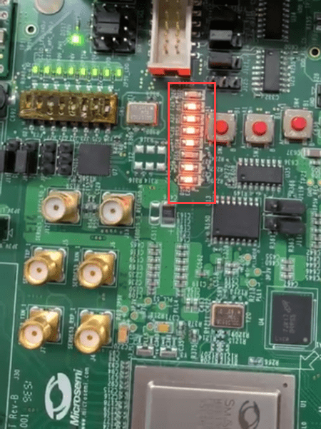
13. After you load the bitstream, the LEDs on the SmartFusion2 board start blinking. You can change the direction of LED blinking by pressing Slide Switch[0].
See Also
You can also select a web site from the following list:
Americas
- América Latina (Español)
- Canada (English)
- United States (English)
Europe
- Belgium (English)
- Denmark (English)
- Deutschland (Deutsch)
- España (Español)
- Finland (English)
- France (Français)
- Ireland (English)
- Italia (Italiano)
- Luxembourg (English)
- Netherlands (English)
- Norway (English)
- Österreich (Deutsch)
- Portugal (English)
- Sweden (English)
- Switzerland
- United Kingdom (English)