このページは前リリースの情報です。該当の英語のページはこのリリースで削除されています。
5 セルのマルチレベル コンバーター
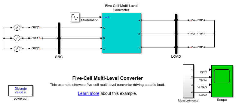
この例では、静的負荷を駆動する 5 セルのマルチレベル コンバーターを示します。
Graham Dudgeon, Senior Consultant, The MathWorks, Inc.

説明
システムは、ダイオード整流器および IGBT H ブリッジ インバーターを含んでいるセルから作成された、三相 5 セルのマルチレベル コンバーター (MLC) から構成されています。MLC は理想的な 60 Hz の三相電源が供給され、100 Hz で静的抵抗/誘導負荷を駆動します。コンバーターのアーキテクチャが取得されます [1]。各セルの Z 字型の入力変換器は相対で 15 度ずつ位相シフトし、第 23 次高調波より下の電源高調波を改善します。H ブリッジ PWM 搬送波は相対で 45 度ずつ位相シフトし、出力電圧の 'スタック' 効果を生成します。コンポーネントのマスク内を表示すると、MLC の変調の性質がはっきりとわかります。
シミュレーション
シミュレーションを開始します。Scope ブロックの電圧のスタック効果を観察します。Powergui の FFT Analysis ツールを使用して、第 23 次高調波より下にはソース電流 ISRC に大きな高調波がないことを確認します。
変調波形を調整して出力電圧の振幅と周波数を変更できます。
参考文献
[1] Wen, J. and Smedley, K.M., 'Synthesis of Multi-Level Converters Based on Single- and/or Three-Phase Converter Building Blocks', IEEE® Transactions on Power Electronics, Vol. 23, No. 3, May 2008.