DSM DAC
R2026bDSM DAC block
To add a block to a model, double-click the canvas and start typing the block name. Then, select the block from the list.
Libraries:
Mixed-Signal Blockset /
ADC /
Building Blocks
Description
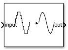
Use the DSM DAC (delta-sigma modulator digital-to-analog converter) block to model a voltage-mode multi-bit DAC with a comprehensive set of real-world non-idealities including gain error, offset error, integral nonlinearity (INL), delay, and clock jitter. You can also choose the output pulse types — non-return-to-zero (NRZ), return-to-zero (RZ), and half-return-to-zero (HRZ). This block enables you to simulate behavioral models of DAC impairments and their effect on system-level performance. It is particularly useful in high-speed, high-resolution data converter and mixed-signal applications.
Note
Use the DSM DAC block only with a delta-sigma modulator (Delta Sigma Modulator or Continuous Time Delta Sigma Modulator) and not as a standalone DAC.
Ports
Input
Output
Parameters
Programmatic Use: Add Block
To add the block programmatically, use the add_block function with one of these library block paths as the source.
"msbAdcFoundation/Sampling Clock Source"
Example: add_block("msbAdcFoundation/Sampling Clock Source","myModel/myBlock",MakeNameUnique="on")
For information about programmatic access to individual block parameters, see the Programmatic Use section of parameter descriptions on this page.
Tips
The block models a multi-bit DAC in CT-DSM feedback paths. While it can accept continuous inputs (performing quantization as a convenience feature), it only models DAC non-idealities. For accurate ADC and DAC modeling, use dedicated ADC and DAC blocks in series.
Version History
Introduced in R2026b

