Hydraulically Operated Remote Control Valve
(To be removed) Normally closed or normally open hydraulically operated remote control valve
The Hydraulics (Isothermal) library will be removed in a future release. Use the Isothermal Liquid library instead.
For more information on updating your models, see Upgrading Hydraulic Models to Use Isothermal Liquid Blocks.
Library
Directional Valves

Description
The Hydraulically Operated Remote Control Valve block represents a hydraulically operated remote control valve as a data-sheet-based model, meaning that most of the model parameters are generally available in catalogs or manufacturer data sheets. Hydraulically operated remote control valves are widely used in hydraulic systems as hydraulic switches, unloading and sequencing valves. You can also use them as pressure-relief and pressure-reducing valves. The block covers both the normally closed and normally open configurations, shown in the following figure.
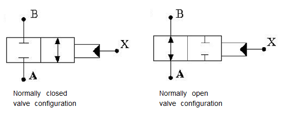
The valve opens (closes) by the pilot pressure. The valve control member remains in its initial position as long as the pilot pressure is lower than the cracking pressure. When cracking pressure is reached, the valve control member (spool, ball, poppet, and so on) is forced off its seat and starts opening the normally closed valve, or closing the normally open valve. The control member displacement is directly proportional to pilot pressure. The member reaches its maximum displacement after the pilot pressure becomes equal or greater than the preset maximum value. The valve maximum area, cracking pressure, and maximum pressure are the key parameters of the block. These three parameters are usually provided in catalogs or data sheets.
In addition to the maximum area, the leakage area is also required to characterize the valve. The main purpose of the parameter is not to account for possible leakage, even though this is also important, but to maintain numerical integrity of the circuit by preventing a portion of the system from getting isolated after the valve is completely closed. An isolated or “hanging” part of the system could affect computational efficiency and even cause failure of computation. Therefore, the parameter value must be greater than zero.
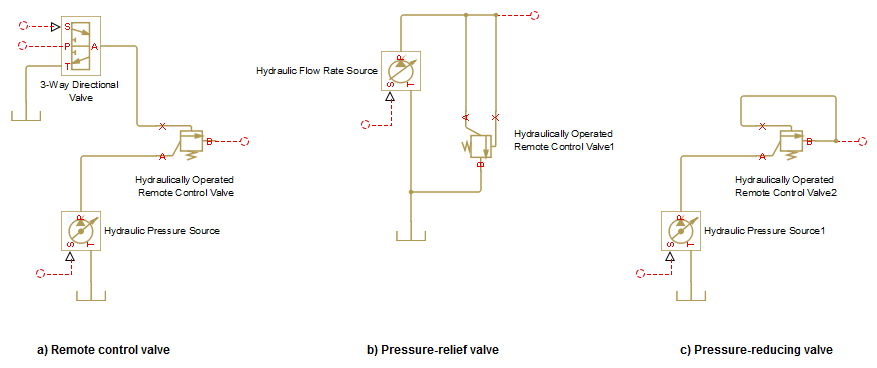
Schematic fragments in the next illustration show some typical valve applications: remote control valve (a), pressure-relief valve (b), and pressure-reducing valve (c).
The flow rate through the orifice is proportional to the orifice opening and the pressure differential across the orifice.
By default, the block does not include valve opening dynamics, and the valve sets its opening area directly as a function of pressure:
Adding valve opening dynamics provides continuous behavior that is more physically realistic, and is particularly helpful in situations with rapid valve opening and closing. The pressure-dependent orifice passage area A(p) in the block equations then becomes the steady-state area, and the instantaneous orifice passage area in the flow equation is determined as follows:
In either case, the flow rate through the valve is determined according to the following equations:
For the normally closed valve, the instantaneous orifice passage area A(p) is computed with the equations:
For the normally open valve, the equations are similar:
The rest of the equations apply to both valve configurations:
where
| q | Flow rate through the valve |
| p | Pressure differential across the valve |
| pA, pB | Gauge pressures at the block terminals |
| pp | Gage pressure at the pilot terminal |
| CD | Flow discharge coefficient |
| ρ | Fluid density |
| τ | Time constant for the first order response of the valve opening |
| t | Time |
| A | Instantaneous orifice passage area |
| A(p) | Pressure-dependent orifice passage area |
| Ainit | Initial open area of the valve |
| Amax | Fully open valve passage area |
| Aleak | Closed valve leakage area |
| pcrack | Valve cracking pressure |
| pmax | Pilot pressure to shift the control member to its maximum |
| pcr | Minimum pressure for turbulent flow, when the block transitions from laminar to turbulent regime |
The minimum pressure for turbulent flow, pcr, is calculated according to the laminar transition specification method:
By pressure ratio — The transition from laminar to turbulent regime is defined by the following equations:
pcr = (pavg + patm)(1 – Blam)
pavg = (pA + pB)/2
where
pavg Average pressure between the block terminals patm Atmospheric pressure, 101325 Pa Blam Pressure ratio at the transition between laminar and turbulent regimes (Laminar flow pressure ratio parameter value) By Reynolds number — The transition from laminar to turbulent regime is defined by the following equations:
where
DH Orifice hydraulic diameter ν Fluid kinematic viscosity Recr Critical Reynolds number (Critical Reynolds number parameter value)
Connections A and B are hydraulic conserving ports associated with the inlet and the outlet of the valve. Connection X is the pilot port, which is a hydraulic conserving port that provides the pilot pressure. The block positive direction is from port A to port B. This means that the flow rate is positive if it flows from A to B, and the pressure differential is determined as .
Basic Assumptions and Limitations
Control member displacement is linearly proportional to pilot pressure.
No flow consumption is associated with the pilot chamber.
No loading on the valve, such as inertia, friction, spring, and so on, is considered.
Parameters
- Valve type
Select the valve configuration:
Normally closed valveorNormally open valve. The default isNormally closed valve.- Maximum passage area
Valve passage maximum cross-sectional area. The default value is
1e-4m^2.- Cracking pressure
Pressure level at which the valve control member is forced off its seat and starts to either open or close the valve, depending on the valve type. The default value is
3e4Pa.- Maximum control member displacement pressure
Pilot pressure at which the valve control member shifts to its maximum displacement and remains there until the pressure falls below this level. Its value must be higher than the cracking pressure. The default value is
1.2e5Pa.- Flow discharge coefficient
Semi-empirical parameter for valve capacity characterization. Its value depends on the geometrical properties of the orifice, and usually is provided in textbooks or manufacturer data sheets. The default value is
0.7.- Laminar transition specification
Select how the block transitions between the laminar and turbulent regimes:
Pressure ratio— The transition from laminar to turbulent regime is smooth and depends on the value of the Laminar flow pressure ratio parameter. This method provides better simulation robustness.Reynolds number— The transition from laminar to turbulent regime is assumed to take place when the Reynolds number reaches the value specified by the Critical Reynolds number parameter.
- Laminar flow pressure ratio
Pressure ratio at which the flow transitions between laminar and turbulent regimes. The default value is
0.999. This parameter is visible only if the Laminar transition specification parameter is set toPressure ratio.- Critical Reynolds number
The maximum Reynolds number for laminar flow. The value of the parameter depends on the orifice geometrical profile. You can find recommendations on the parameter value in hydraulics textbooks. The default value is
12, which corresponds to a round orifice in thin material with sharp edges. This parameter is visible only if the Laminar transition specification parameter is set toReynolds number.- Leakage area
The total area of possible leaks in the completely closed valve. The main purpose of the parameter is to maintain numerical integrity of the circuit by preventing a portion of the system from getting isolated after the valve is completely closed. The parameter value must be greater than 0. The default value is
1e-12m^2.- Opening dynamics
Select one of the following options:
Do not include valve opening dynamics— The valve sets its orifice passage area directly as a function of pressure. If the area changes instantaneously, so does the flow equation. This is the default.Include valve opening dynamics— Provide continuous behavior that is more physically realistic, by adding a first-order lag during valve opening and closing. Use this option in hydraulic simulations with the local solver for real-time simulation. This option is also helpful if you are interested in valve opening dynamics in variable step simulations.
- Opening time constant
The time constant for the first order response of the valve opening. This parameter is available only if Opening dynamics is set to
Include
                            valve opening dynamics
. The default value is0.1s.- Initial area
The initial opening area of the valve. This parameter is available only if Opening dynamics is set to
Include valve opening dynamics. The default value is1e-12m^2.
Global Parameters
Parameters determined by the type of working fluid:
Fluid density
Fluid kinematic viscosity
Use the Hydraulic Fluid block or the Custom Hydraulic Fluid block to specify the fluid properties.
Ports
The block has the following ports:
AHydraulic conserving port associated with the valve inlet.
BHydraulic conserving port associated with the valve outlet.
XHydraulic conserving port that acts as the control port and provides the pilot pressure.