Use Intel AVX2 Code Replacement Library to Generate SIMD Code from Simulink Blocks
Note
This workflow requires an Embedded Coder® license.
To configure a Simulink® model to generate SIMD code using Intel® AVX2 code replacement library:
In the Apps tab of the Simulink model toolstrip, click the Embedded Coder app.
In the C Code tab that opens, click Settings.
In the Hardware Implementation pane, set the Device vendor (Simulink) parameter to
Intel. Set the Device type (Simulink) parameter tox86-64(Windows 64),x86-64(Linux 64), orx86-64(Mac OS X).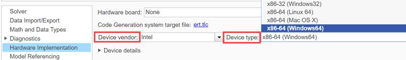
In the Configuration Parameters dialog box that opens, in the Code Generation pane, set the System target file to
ert.tlc.Note
This workflow does not support the MinGW C/C++ compiler. You can choose any other compiler listed in Supported Compilers. To select a different compiler that is installed on your machine, run
mex -setupin the MATLAB® command prompt and follow the instructions.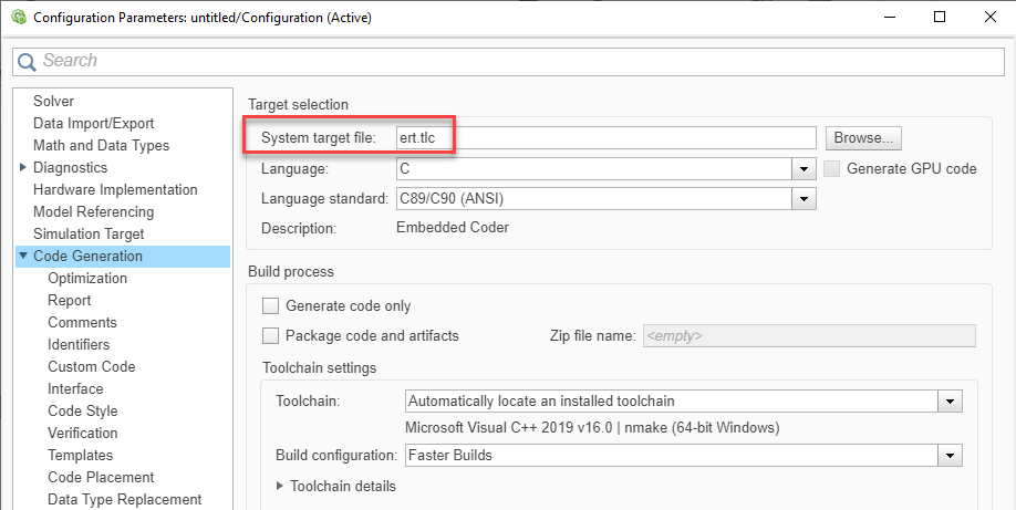
Under Code Generation, in the Interface pane, set the Code Replacement libraries to either
DSP Intel AVX2-FMA (Windows),DSP Intel AVX2-FMA (Linux), orDSP Intel AVX2-FMA (Mac). Using these libraries, you can generate high performance SIMD code. For more information on Code Replacement Libraries, see What Is Code Replacement? (Embedded Coder).
In the model window, initiate code generation and the build process for the model by using one of these common options:
Click the Build Model button in the C Code tab.
Press Ctrl+B.
For an example on how to select a system target file for a Simulink model and how to generate C code for embedded systems, see Generate Code Using Embedded Coder (Embedded Coder).
The SIMD code is generated using Intel AVX2-FMA technology. The Intel AVX2 SIMD intrinsics significantly improve the performance of the code generated from the supported algorithms on Intel platforms, in most cases meeting or exceeding the performance of the simulation and plain C code.
To generate SIMD code using the model configuration parameter Leverage target hardware instruction set extensions, see Use Target Hardware Instruction Set Extensions to Generate SIMD Code from Simulink Blocks for Intel Platforms.
Compare the Performance of SIMD Code with Generated Plain C Code
Consider this Simulink model that models a digital communication system. The model contains a root-raised cosine filter on the transmitter and the receiver side, a couple of FIR Interpolation and FIR Decimation blocks to increase and decrease the sample rate of the signal, respectively, and an additive white Gaussian noise (AWGN) communication channel to transmit the signal. The root-raised cosine filters on both sides perform matched filtering. The combined response of the two root-raised cosine filters forms a raised-cosine filter, which helps in minimizing the intersymbol interference (ISI). Due to matched filtering, the signal received at the output has a high signal to noise ratio (SNR) and low probability of error. To confirm, view the output in the constellation diagram that follows.
Open the ex_qam_matchedfilter model.

In the Modeling tab of the model, click Model Settings. In the configuration parameters window that opens, under Code Generation in the Interface pane, set Code replacement libraries to None. Build the model and this setting generates plain C code executable in the current MATLAB directory. However, if you specify a Code generation folder (Simulink) in Simulink preferences, building the model generates plain C code executable in the specified folder. Measure the time it takes to run the executable.
tic;
system('ex_qam_matchedfilter');
tplain = toc
tplain =
37.4883
Repeat the process by setting the Code replacement libraries to DSP Intel AVX2-FMA (Windows), DSP Intel AVX2-FMA (Linux), or DSP Intel AVX2-FMA (Mac), depending on the platform of the machine you are using. Build the model and measure the time it takes to run the generated AVX2 executable.
tic;
system('ex_qam_matchedfilter');
tavx2 = toc
tavx2 =
8.29
The generated SIMD code is around 4.5x compared to the plain C code on a Windows® 10 machine.
tplain/tavx2
ans =
4.5221
Related Topics
- Simulink Blocks in DSP System Toolbox that Support SIMD Code Generation
- Use Target Hardware Instruction Set Extensions to Generate SIMD Code from Simulink Blocks for Intel Platforms
- Use Intel AVX2 Code Replacement Library to Generate SIMD Code from MATLAB Algorithms
- Generate Code Using Embedded Coder (Embedded Coder)
You can also select a web site from the following list:
Americas
- América Latina (Español)
- Canada (English)
- United States (English)
Europe
- Belgium (English)
- Denmark (English)
- Deutschland (Deutsch)
- España (Español)
- Finland (English)
- France (Français)
- Ireland (English)
- Italia (Italiano)
- Luxembourg (English)
- Netherlands (English)
- Norway (English)
- Österreich (Deutsch)
- Portugal (English)
- Sweden (English)
- Switzerland
- United Kingdom (English)