Teaching Mechatronics with MATLAB, Simulink, and Arduino Hardware
By Joshua Hurst, Rensselaer Polytechnic Institute
Mechatronics is such a broad discipline that teaching it at the undergraduate level presents a significant challenge. We must give our students a foundation in theoretical analysis that spans mechanical, electrical, and computing domains. At the same time, we must provide hands-on projects that integrate sensors, actuators, and embedded real-time control systems.
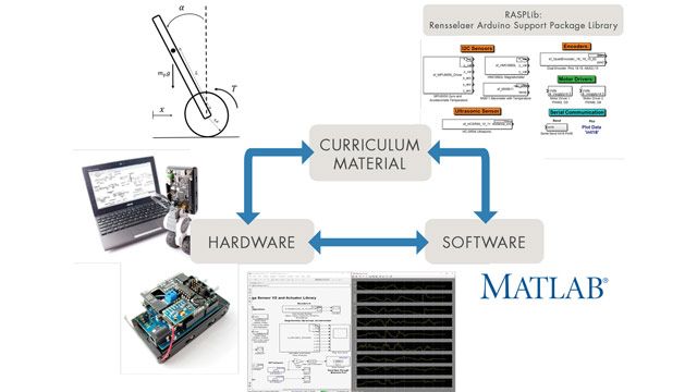
At Rensselaer Polytechnic Institute (RPI), my colleagues and I have addressed this challenge with a mechatronics curriculum that incorporates a take-home kit for lab assignments and course projects. The Rensselaer Mechatronics Kit includes an Arduino® based microcontroller, a DC motor, a set of sensors, and MATLAB® and Simulink® software (Figure 1).
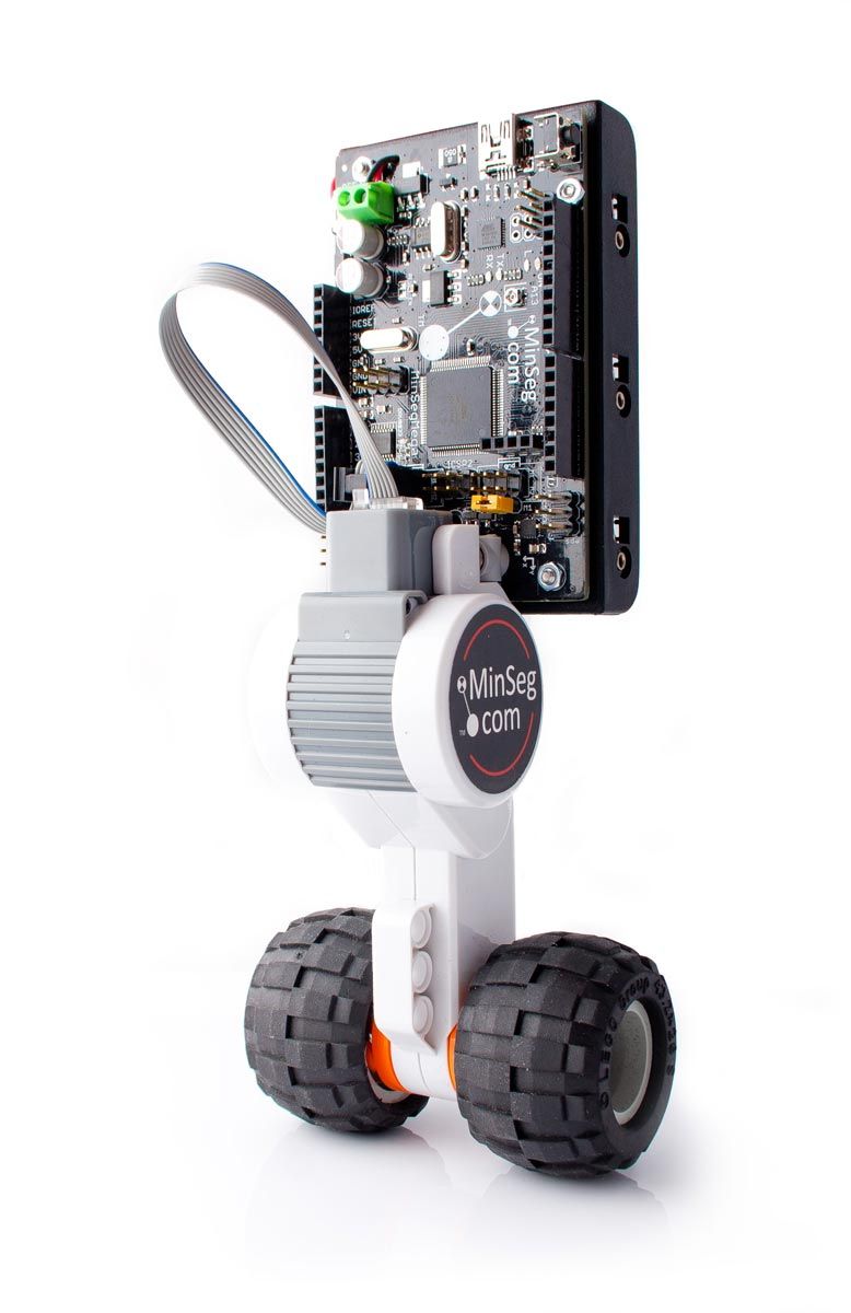
In our Mechatronics course, fourth-year undergraduates use the kit to design and implement a real-time control system for MinSeg, a two-wheeled, self-balancing robot (Figure 2).
MATLAB, Simulink, and Simulink Support Package for Arduino Hardware enable the students to focus on high-level system design for inverted pendulum control even as they learn to deal with real-world effects such as saturation, discretization, and measurement delays.
MATLAB and Simulink at Rensselaer
Most students enter the fourth-year mechatronics course already familiar with MATLAB because the tools are used throughout the RPI engineering curriculum. For example, engineering students are required to take an introductory programming course that is offered in both C and MATLAB. RPI also offers Introduction to Mechatronics Hardware and Software, in which first- and second-year students use the Rensselaer Mechatronics Kit with MATLAB and Simulink to complete lab assignments similar to but simpler than those in my fourth-year course. I teach other fourth-year courses: Design Optimization: Theory and Practice, and Machine Dynamics, which rely heavily on MATLAB, and Multidisciplinary Capstone Design, in which many students use MATLAB and Simulink to solve design problems spanning multiple engineering domains. Next semester, we plan to incorporate MATLAB, Simulink, and the Rensselaer Mechatronics Kit into Modeling and Control of Dynamic Systems, a core course required for all mechanical, aerospace, and nuclear engineers at RPI.
Because RPI has a Total Academic Headcount license, my colleagues and I can integrate assignments to be completed in MATLAB or Simulink into any course, knowing that all students have easy access to the tools.
What Inspired the Inverted Pendulum Project and the Mechatronics Kit
As a student at RPI, I took a controls course taught by Dr. Kevin Craig, a mechatronics pioneer. Dr. Craig demonstrated a rotary inverted pendulum system that balanced a rigid link on one end. I remember thinking it was one of the most amazing things that I had ever seen, and I was inspired to learn what it would take to make a system like that work. When I began teaching at RPI, I wanted to design lab exercises that sparked this same enthusiasm in my students.
Many of the existing lab assignments in the mechatronics course required students to write C code by hand. Maintaining the labs required a great deal of instructor effort, and students spent much of their time debugging code instead of learning to apply the concepts learned in class. All too often, students reverted to trial-and-error rather than theory-based analysis to achieve the desired experimental outcomes.
I could have addressed this issue by simplifying the lab assignments—minimizing real-world effects in order to demonstrate the theory. My view, however, is that students need to see that real life doesn’t always match the theory.
I decided to revamp the lab curriculum with a focus on DC motor control. DC motors are ideal for mechatronics labs because they are inexpensive, are widely used in industry, and neatly couple electrical and mechanical systems. Low-cost motors and microprocessors were both readily available, but I needed to enable students to use them in labs without spending most of their time coding and debugging.
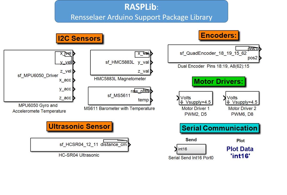
When I learned how easy it was to program an Arduino with MATLAB and Simulink, I knew I had a path forward: I simply connected the Arduino hardware to my laptop with a USB cable, and after a few clicks, I was running a Simulink model on the hardware. At this point, all I lacked was a way for students to build Simulink models that could access the various sensors and actuators needed to complete the labs. To address this, I developed Rensselaer Arduino Support Package Library (RASPLib), which contains custom Simulink blocks for all the sensors and actuators in the Rensselaer Mechatronics Kit, including a three-axis accelerometer, gyroscope, and magnetometer, as well as a DC motor and amplifier (Figure 3).
Using the Mechatronics Kit to Complete Lab Assignments
The first few lab assignments in Mechatronics introduce the Rensselaer Mechatronics Kit. For example, in an early lab the students use Simulink to program the Arduino microprocessor to make an LED blink. Once the students are comfortable working with the hardware, they begin tackling more complex problems, including motor control and, later, the inverted pendulum robot.
For the robot project, I ask the students to design a controller that uses the sensors and motor in the kit to balance the Arduino board on two wheels. To help them appreciate the complexity of this challenge, I first let them come up with a controller design on their own. I then lead them through a dynamic system investigation process with MATLAB and Simulink (Figure 4).
In this process, the students first describe the physical system and a set of simplifying assumptions. They then develop an electrical schematic and a free body diagram of the system’s electrical and mechanical components. Applying Kirchoff’s voltage law and Newton’s laws, the students then generate a mathematical model of the system comprising two coupled nonlinear differential equations.
Since the mathematical model alone does not show the students how the system behaves, I have them analyze the differential equations in MATLAB, solving for the step response and the free response. They run experiments using the actual hardware, and compare the results with results produced by the mathematical model. If the simulated response doesn’t match the experimental response, the students either adjust system parameters in the model or re-evaluate their assumptions—perhaps by incorporating friction or backlash effects into the model.
The next step in the process is to develop a controller. The students begin by linearizing the nonlinear equations of motion to obtain a linear state-space model. They then develop a linear quadratic regulator (LQR) full-state feedback controller model in Simulink using standard Simulink blocks as well as gyroscope, encoder, and motor blocks from the RASPLib library (Figure 5).
After running simulations in Simulink with the mathematical plant model, the students use Simulink external mode to run their controller model on the Arduino hardware. In this mode they can interact with their controller design as it is running, which makes debugging and tuning the controller easy. When they are ready to conduct final tests, the students deploy their Simulink model to the Arduino hardware model, enabling the robot to operate independently.
Frustration Gives Way to Inspiration
Early in the Mechatronics course, I tell the students that they will not be learning many new concepts. Instead, they’ll be recombining much of what they learned about hardware, software, and control theory in their earlier coursework. Nevertheless, most students find aspects of the course—including learning to model and mitigate real-world nonlinear system effects—very challenging. Inevitably, they are frustrated when they can’t get their robots to balance, but when they do finally make the robot work, their eyes light up and the frustration melts away. As my Linköping University colleague Johan Löfberg commented, “Labs are done, students very happy. . . .One student told me that when she saw the robot on the first lecture, she could not imagine that she would be able to balance it, but then on the final lab she realized she had built most of the controller, and here it was, standing up.” (Figure 6).
The growing popularity of the Mechatronics course is one indication that my students recognize the value in this approach and that I’ve managed to inspire at least some of them, just as I was inspired as an undergraduate. The course now has a waiting list, and instead of offering only one session in the fall, we will soon be offering two sessions every semester.
Acknowledgements
I would like to acknowledge the contributions of my colleague, Sandipan Mishra, who has been instrumental in the development of the mechatronics curriculum at RPI, and my mechatronics mentor, Dr. Kevin Craig.
Published 2017 - 93122v00


