Developing and Testing AUTOSAR Software Components and Complex Device Drivers with Model-Based Design
By Enric Valencia, Ph.D., and Joan Albesa, Ph.D., IDNEO
AUTOSAR is already a de facto industry standard for the design and implementation of software for automotive applications. The open, standardized software architecture of AUTOSAR helps OEMs and suppliers collaborate on projects because most application logic can be implemented in software components (SW-C) in an application layer that interfaces with a standard run-time environment (RTE) rather than with ECU hardware (Figure 1).

Figure 1. AUTOSAR software architecture.
While some AUTOSAR projects that our team works on involve a set of SW-C that runs on top of the RTE, others require more direct access to the ECU microcontroller via a complex device driver (CDD) operating under the RTE. CDD development has historically presented a greater engineering challenge because CDD code must interact not only with the RTE but also with basic software (BSW) beneath the RTE.
We've used Model-Based Design for SW-C development for some time. Model-Based Design supports a well-established and mature workflow in which software component description ARXML files generated by AUTOSAR authoring tools are used to create an initial Simulink® representation of the design. We recently worked with MathWorks Consulting Services to extend our capabilities in this area to CDD development. Now, instead of hand-coding CDD software, we use Model-Based Design for both SW-C and CDD.
Using the same workflow and toolset for both types of AUTOSAR software not only reduces costs, training time, and maintenance overhead, it enables us to move engineers easily between SW-C and CDD teams. More importantly, by using Model-Based Design for all AUTOSAR projects, we have cut development time by at least 50% while increasing the number of defects identified early in the design phase and reducing the number of defects found in hardware tests and beyond.
A Top-Down Approach to Component Design
Using our AUTOSAR authoring tool, DaVinci Developer, we define the software component architecture and interfaces and then export software component description ARXML files. Following a top-down approach, we import these files into Simulink to create a skeleton model with all the interfaces set up exactly as we defined them in DaVinci Developer.
We use this skeleton model as a basis for modeling and simulating the application control logic in Stateflow® (Figure 2). We link elements in our Simulink model to related requirements, managed in IBM® Rational® DOORS®. Establishing traceability in this way supports impact analysis and documentation activities for certification.
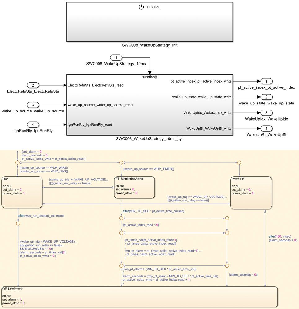
Figure 2. Top: Skeleton model. Bottom: Completed model.
Code Generation and Verification
After running simulations to check our initial design, we conduct formal tests. In the past, MATLAB® scripts served as our verification suite for AUTOSAR projects. While this in-house framework worked well, it required a significant amount of effort to develop and maintain. With support from a MathWorks consultant, we evaluated Simulink Test™ as an alternative. We found that Simulink Test provided the same test functionality as our MATLAB scripts while eliminating the maintenance burden.
We now use Simulink Test to define test suites and test cases as well as to automate the generation of test harnesses (Figure 3). We primarily run baseline tests in which we compare simulation outputs with expected outputs. Nonetheless, equivalence tests with the software-in-the-loop (SIL) version of the model are also run for further verification.
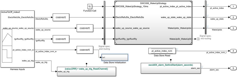
Figure 3. Sample test harness generated with Simulink Test.
Following simulation-based tests, we generate MISRA®-compliant C code from our models with Embedded Coder®. The generated code is ready for use on our target Renesas® microcontroller, and does not require any postprocessing. As part of our verification process we collect code metrics and check for divide-by-zero, overflow, and other run-time errors using Polyspace® static code analysis tools.
Shorter Development Time, Improved Quality, and Other Advantages
Our use of Model-Based Design for the development of AUTOSAR CDDs and SW-Cs has led to significant improvements in areas that affect IDNEO’s business opportunities. One such area is customer collaboration. When our customers use Simulink, we can work with their models directly, which removes the ambiguity inherent in natural language requirements and can cut development time in half. In addition, with the ability to develop CDDs using Model-Based Design instead of hand-coding, we have greater flexibility to meet our customers’ needs because we can implement features using a SW-C, a CDD, or both, depending on the specific use case.
Sometimes, customers provide us with AUTOSAR components that they have developed and ask us to integrate them into a larger system, potentially with other third-party components. In these cases, we use the ARXML definition of the component’s interfaces to simplify the integration process, reducing development time by as much as 70%.
Compared with past projects of similar scope on which we did not use AUTOSAR and Model-Based Design, we now have a much shorter time-to-market—from one year to six months, in some cases. In addition, we are able to detect errors earlier, enabling us to find and fix about 80% of errors in the design phase instead of in hardware testing.
We are looking to refine our Model-Based Design workflow and become more agile by adopting continuous integration and continuous delivery practices. We have already made progress in this direction by incorporating Polyspace into our Jenkins continuous integration (CI) pipeline. We also plan to integrate test suites from Simulink Test into our Jenkins CI pipeline in the near future.
Published 2018